Congratulations on your
purchase of the Maretron VMM6 Series Contura Digital Switch Module, 6 Rocker.
Carling Technologies has proudly designed and built your VMM6 to the highest
standards for reliability and accurate service.
The VMM6 is a sealed, IP68
rated, digital switch module ready to
deliver years of dependable operation within the harsh demands of the marine
environment. The VMM6 features Carling’s popular Contura rocker switch styles. The
VMM6 reduces installation time and the complexity and cost of traditional
wiring harnesses by utilizing NMEA 2000® CAN interface technology and screwless,
snap-in mounting tabs. With internal
optical interrupt switches replacing traditional mechanical switch contacts,
the VMM6 has an unrivaled product life cycle.
The VMM6 connects directly to an NMEA 2000® network through
the use of the VMM to NMEA 2000® Adapter Cable. Configure
the VMM6 by using a Maretron USB100 or IPG100 tethering the NMEA2000® network
to a PC running N2KAnalyzer. Control MPower and other Maretron systems with the
VMM6 through an NMEA 2000® Network.
Using standard NMEA 2000® messaging, the VMM6 can illuminate any of its 12 blue
LED lights for status of circuit state or for use as backlighting.
The VMM6 is available in 6 standard configurations.
Custom configurations are available with a minimum order quantity of 100
pieces.
Please carefully read and follow these instructions
for installation, configuration, and usage of the Maretron VMM6 module to
ensure optimal performance.
·
Mechanical Detent Provides Tactile
and Audible Switch Operation
·
Configurable Operation and Appearance Aspect
- Accepts Aftermarket Switch Actuators
- All Switch Positions have Blue LED’s
- Horizontal or Vertical Mounting Options
- Screwless, Snap-In Mounting
- IP68 Rated with Plug for Unused Connector
- NMEA 2000 CAN Protocol
- LED Feedback of Controlled Circuit State
- Low Current Consumption (Max Current 150mA)
- NMEA 2000 LEN: 3
- Operating Voltage: 9 - 32 VDC
- Endurance Tested to Reach Minimum of 250,000 Operations
For Technical Specifications please refer to page 13
The mechanical throw type for
each switch must be programmed into the module via CAN message(s). Switch
position will be reported via the NMEA2000® Standard 127501 “Binary Status
Report” message. To allow each switch to report up to three discrete positions,
the top and bottom switch positions will be considered separate binary (on or
off) switches and will be numbered as follows:

There is a total of twelve
blue LEDs, each configurable via CAN message to act as a backlight or a function
indicator. The LEDs are located under the top and bottom of each actuator. All
LEDs set as backlights will share the same brightness and on/off values. LEDs
set as status indicators can be tied to a channel of any device on the CAN
network that reports the NMEA2000® standard “Binary Status Report” message.
When the associated channel reports it is in the “on” state, the LED will be
turned on. When the associated channel reports it is in the “off” state, the LED
state will turn off.
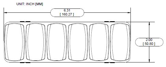
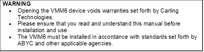
Figure 1 - Hardware
Description Front View
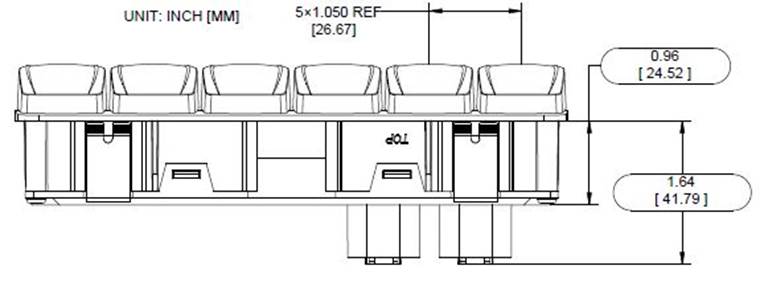
Figure 2 - Hardware
Description Top View
Figure 3 - Hardware
Description Side View
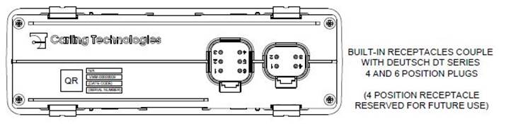
Figure 4 - Hardware
Description Back View
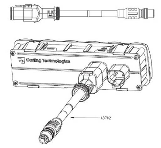
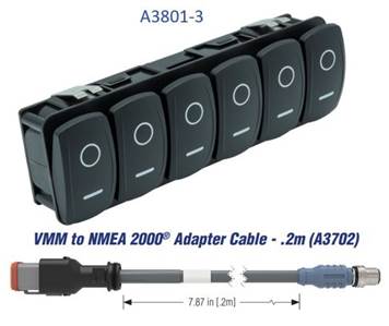
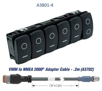
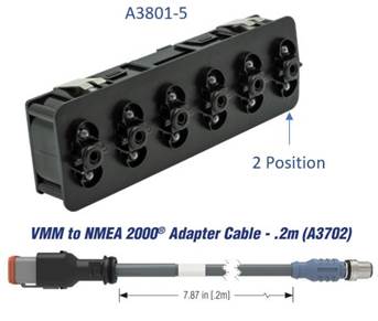
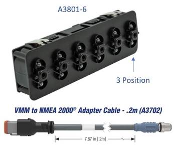
Figure 5 – Optional VMM
to NMEA 2000® Adapter Cable - .2m (A3702)
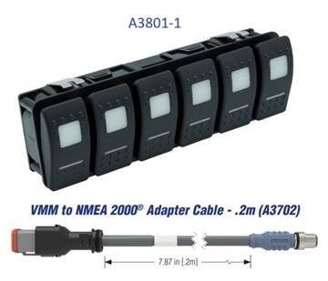
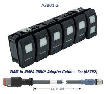
The VMM6 can be ordered in 6 different convenient
configurations as outlined in Table 1.
Custom Configurations are available with a minimum order
of 100 units.
Contact [email protected] for a custom quotation.
Table 1 – Ordering
Options
|
PART NUMBER
|
DESCRIPTION
|
|
A3702
|
VMM
to NMEA 2000® Adapter Cable - .2m (3702)
|
|
A3801-1
|
Contura
II (ALL Position Momentary ON) w/ VMM to NMEA 2000® Adapter Cable .2m
|
|
A3801-2
|
Contura
II (Right Switch 3-Position) w/ VMM to NMEA 2000® Adapter Cable .2m
|
|
A3801-3
|
Contura
V (All Positions Momentary ON) w/ VMM to NMEA 2000® Adapter Cable .2m
|
|
A3801-4
|
Contura
V (Right Switch 3-Position) w/ VMM to NMEA 2000® Adapter Cable .2m
|
|
A3801-5
|
No
Actuators (ALL Positions Momentary ON) w/ VMM to NMEA 2000® Adapter Cable .2m
|
|
A3801-6
|
No
Actuators (Right Switch 3-Position) w/ VMM to NMEA 2000® Adapter Cable .2m
|
Installing the Maretron VMM6 involves the following steps.
When unpacking the box containing the Maretron VMM6, you
should find the following items:
1 – VMM6 Digital Switch Module
1 – VMM6 User’s Manual on USB
flash drive
1 – VMM6 Panel
Installation Template
1 –
Warranty Registration Card
1 – A3702 VMM
to NMEA 2000® Adapter Cable - .2m
If any of these items are missing or damaged, please
contact Maretron Technical Support
(please refer to page 16 for contact information).
Please consider the following when choosing a mounting
location.
- The
VMM6 is waterproof, so it can be installed in a damp or dry location.
- Consider
mounting depth. (6” recommended clearance needed for proper cable bend
radius)
- The
VMM6 is temperature-rated to 85°C (185°F). Mount VMM6 away from engines or
engine rooms where the operating temperature exceeds the specified limit.
- After
mounting, ensure cable strain relief.
Locate the panel mounting template supplied with the VMM6.
After cutting the panel mounting hole, simply press the VMM6 into panel cutout.
The VMM6 mounting tabs will securely hold the unit into place provided the
minimum panel thickness of 0.06” (1.5 mm) is present. The use of silicone
sealant is acceptable to prevent water intrusion behind the unit and in some
cases to secure the unit. Do not use permanent adhesive to secure unit. Certain
adhesives such as methacrylate will cause cracking of the plastic enclosure.
Adhesive use for installation will void warranty of VMM6 unit. For reference to
the needed panel cutout dimensions see Figure 6.
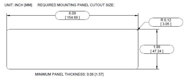
Figure 6 – Mounting
Panel Cutout Dimension
Connecting the VMM6 consists of plugging the unit into the
vessel’s NMEA 2000® network. The unit can be connected to the NMEA 2000 network
directly with the 6 position Deutsch DT Series receptacle molded into the unit
or via use of the A3702 VMM to NMEA 2000® Adapter
Cable.
Table 2 – 4 Position Connector Pin Description
|
Connector Pin
No. (Location)
|
Description
|
|
1
|
Reserved for
Future Use
|
|
2
|
Reserved for
Future Use
|
|
3
|
Reserved for
Future Use
|
|
4
|
Reserved for
Future Use
|
Table 3 – 6 Position
Connector Pin Description
|
Connector
Pin No. (Location)
|
Description
|
|
1
|
NET_L (CAN_L)
|
|
2
|
NET_H (CAN_H)
|
|
3
|
Unused
|
|
4
|
Unused
|
|
5
|
NET_C (Batt. -)
|
|
6
|
NET_S (Batt. +)
|
The NMEA 2000® connector is the round five-pin male
connector found on the VMM to NMEA 2000® Adapter Cable This
connector is known as a DeviceNet micro connector. You connect the VMM6 to a
NMEA 2000® network using a Maretron NMEA 2000® cable (or compatible cable) by
connecting the female end of the cable to the male NMEA 2000 connector on the VMM to NMEA 2000® Adapter Cable (note the key on the
male connector and keyway on the female connector). Be sure the cable is
connected securely and that the collar on the cable connector is tightened
firmly. Connect the other end of the cable by plugging into the 6 position
connector on the rear of the VMM6, applying pressure until the connector latch
clicks. The VMM6 is designed so that you can plug or unplug it from an NMEA
2000® network while the power to the network is connected or disconnected.
Please follow recommended practices for installing NMEA 2000® network products.
NMEA 2000 connections can be made using pre-assembled
leads or may be made using field attachable connectors and cables (See: Figure 7).

Figure
7 - NMEA 2000 Connectors
Please refer to the Maretron website (www.maretron.com/products/cabling.php
) for relevant products.
The VMM6 transmits
data over an NMEA 2000® network as it is shipped from the factory. The
default device instance is “Instance 51”. The default data instance whose state
is reflected by the LED’s on the VMM6 is “Instance 32”. The unit will pair with
Maretron CLMD12 and CLMD16 to toggle each unit’s first 6 ECB’s ON and OFF. If
more than one CLMD12, CLMD16 or one of each unit is on the same NMEA 2000®
network the VMM6 unit will have to be configured. Depending on desired switch
control, default configuration may not work for your application and custom
configuration will be needed. The VMM6 is configured using Maretron N2KAnalyzer®. The
following sections describe the configurable parameters of the VMM6.
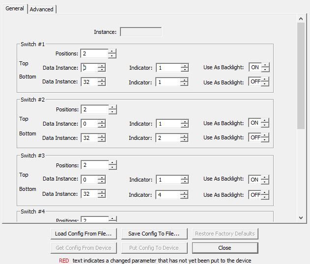
Figure 8 – General
Tab Dialog Box
When connected to a NMEA 2000® network this read-only
field will indicate the indicator bank instance value that will be transmitted
with the switch status in the 127501 Binary Status Report status message. To
change the value of this field, change the value of the VMM6 device instance,
as shown in Advanced Tab.
The VMM6 has six switches. The top and bottom of each
switch has a separate indicator output number. Reference the indicator number
needed from
Table 4 – Indicator
Reference Number
|
Switch Number
|
Top Indicator Number
|
Bottom Indicator Number
|
|
1
|
1
|
2
|
|
2
|
3
|
4
|
|
3
|
5
|
6
|
|
4
|
7
|
8
|
|
5
|
9
|
10
|
|
6
|
11
|
12
|
Each switch has a “Positions” setting which controls its
behavior, and settings which control the lighting of the LED’s behind the top
and the bottom of each switch.
There are two possible settings for this parameter that
control the behavior of the switch:
2 Position: The rocker switch acts as a
two-position toggle switch. When powered on, the indicator for the top of the
switch will transmit the state OFF, and the indicator for the bottom of the
switch will transmit the state ON, and these two values will remain the same
until the top of the switch is pressed. When the top of the switch is pressed,
the indicator for the top of the switch will transmit the state ON, and the
indicator for the bottom of the switch will transmit the state OFF, and these
two values will remain the same until the bottom of the switch is pressed. When
the bottom of the switch is pressed, the indicator for the top of the switch
will transmit the state OFF, and the indicator for the bottom of the switch
will transmit the state ON, and these two values will remain the same until the
top of the switch is pressed.
3 Positions: The rocker switch acts as two
momentary switches. When powered on, the indicator for the top of the switch
will transmit the state OFF, and the indicator for the bottom of the switch
will also transmit the state OFF. When the top of the switch is pressed, the
indicator for the top of the switch will transmit the state ON as long as the
top of the switch is pressed. When the top of the switch is released, the indicator
for the top of the switch will again transmit the state OFF. When the bottom of
the switch is pressed, the indicator for the bottom of the switch will transmit
the state ON as long as the bottom of the switch is pressed. When the bottom of
the switch is released, the indicator for the bottom of the switch will again
transmit the state OFF.
If the Use As Backlight
option is deselected, this Data Instance and Indicator
will be the instance information in which the VMM6 will be tethered to via PGN.
The LED behind the corresponding switch will be lit or
flashing whenever the Indicator that corresponds to the selected Data
Instance is transmitting an On or fault state on the network. The LED
on the switch will be dark otherwise.
(If the “Use As Backlight” option is selected the value of
these fields will be ignored.)
If this option is selected, then the LED behind the top (or
bottom, as appropriate) of the switch will be lit at all times, and the “Data
Instance” and “Indicator” fields will be ignored.
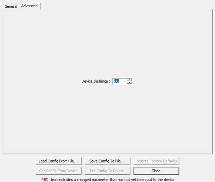
Figure 9
– Advanced Tab Dialog Box
This tab contains the Device Instance setting; If
there are multiple instances of this device on a network, each would be set to
a separate instance.
Regular maintenance is important
to ensure continued proper operation of the Maretron VMM6. Perform the
following tasks periodically:
• Clean the unit with a soft cloth. Do not use chemical
cleaners as they may remove paint and markings or may corrode the CLMD16
enclosure or seals. Do not use any astringent cleaners such as acetone, MEK,
Alcohol, Etc. These cleaners will deteriorate the VMM6 unit’s casing and
actuators.
• Ensure that the unit is mounted securely and cannot be
moved relative to the mounting surface.
• Check the security of the cable connected to the NMEA
2000® connector and tighten if necessary.
If you notice
unexpected operation of the Maretron VMM6, follow the troubleshooting
procedures in this section to remedy simple problems. If these
steps do not solve your problem,
please contact Maretron Technical Support. Refer to page 16 for contact information.
Table 5 -
Troubleshooting Symptoms and Check Procedure
|
Symptom
|
Troubleshooting Procedure
|
|
VMM6 Module
Un-Responsive
|
• Check Connections to VMM to NMEA 2000® Adapter Cable.
• Using a Maretron USB100 or Maretron IPG100, connect
to the NMEA 2000® network and ensure device is configured.
|
|
Any other problems
|
• Please refer to the VMM6 product page on the Maretron website for additional
troubleshooting suggestions.
|
As Carling is
constantly improving its products, all specifications are subject to change
without notice.
|
Parameter
|
Comment
|
|
NMEA 2000® Standard
|
Certified
|
|
CE Mark
|
Recreational Craft Directive 2014/35/EU
|
|
Description
|
PGN #
|
PGN Name
|
Default
Rate
|
|
Periodic Data PGNs
|
127501
|
Binary Status Report
|
1 time / 15 seconds and on
switch change
|
|
Response to Requested PGNs
|
126996
|
Product Information
|
N/A
|
|
126998
|
Configuration Information
|
N/A
|
|
065300
|
Proprietary
|
N/A
|
|
Protocol PGNs
|
059392
|
ISO Acknowledge
|
N/A
|
|
059904
|
ISO Request
|
N/A
|
|
060928
|
ISO Address Claim
|
N/A
|
|
065240
|
ISO Address Command
|
N/A
|
|
126208
|
NMEA
Request/Command/Acknowledge
|
N/A
|
|
126993
|
Heartbeat
|
1 time / 60 seconds
|
|
Parameter
|
Value
|
Comment
|
|
Operating Voltage
|
9 to 32 VDC
|
|
|
Power Consumption
|
150 mA
|
NMEA 2000® Interface
|
|
Load Equivalence Number (LEN)
|
3
|
NMEA 2000® Spec.
(1LEN = 50 mA)
|
|
Communication
|
CAN 2.0b
|
NMEA 2000® Interface
|
|
Programming
|
Proprietary
|
Via Maretron USB100 or IPG100
|
|
Insulation Resistance
|
ISO 16750-2
|
500VDC with a
duration of 60s
|
|
Electrical Endurance
|
Minimum 250,000
Operations
|
50k cycles at Tmin, 150k cycles at Tnom, 50k cycles
at Tmax
|
|
Parameter
|
Value
|
Comment
|
|
Size
|
6.31” x 2.0” x 2.25”
(160.27mm x 50.8mm x 58.49mm)
|
|
|
Weight
|
0.5 lb. (0.22 kg)
|
|
|
Material
|
Housing - Acetal, UV
stabilized Back Cover - Acetal, UV stabilized Rocker – Polycarbonate / Nylon
Mounting Clips – Stainless steel
|
|
|
Functions
|
Actuator function varies
with PN selection.
|
A3801-1 (ALL Position Momentary ON)
A3801-2 (Right Switch is 3 Position)
A3801-3 (All Positions Momentary ON)
A3801-4 (Right Switch is 3 Position)
A3801-5 No Actuators (ALL Positions Momentary ON)
A3801-6 No Actuators (Right
Switch 3 Position)
|
|
Illumination
|
12- Independent LEDs
|
1- Located under each actuator throw
|
|
Dimming
|
N/A
|
|
|
Connection
|
1- Deutsch DT-Series 4 pin receptacle
1-
Deutsch DT-Series 6 pin
receptacle
|
|
|
Mounting
|
Front panel
press-in Installation and frond panel removable
|
|
|
Parameter
|
Value
|
|
Operating Temperature
|
-40°C to 85°C
|
|
Ingress Protection
|
IP68
|
|
Storage Temperature
|
-40°C to 85°C
|
|
Ignition Protection
|
Ignition Protected
|
|
Parameter
|
Standard
|
Conditions
|
|
High Temperature Soak
|
EN 60068-2-2:2007
|
96hrs. @ 85°C
|
|
Low Temperature Soak
|
EN 60068-2-1:2007
|
96 hrs. @ -40°C
|
|
Temperature Cycling (Operating)
|
IEC 60068-2-14:2009
|
-40°C - 85°C (2 cycles of 8 hrs.)
|
|
Temperature Shock (Storage)
|
IEC 60068-2-14:2009
|
Tmin = -40°C, Tmax = 85°C
|
|
Simulated Solar Radiation
|
EN 60068-2-5:2010
(Procedure B)
|
10 days @ 40°C
|
|
Ignition Protection
|
ISO 8846
|
|
|
Altitude (Transport)
|
EN 60068-2-13:1999
|
ALTmin = Sea Level, ALTmax = 13600m
|
|
Humidity (Soak)
|
EN 60068-2-78:2002
|
RH = 93% +/-3%, Exposure
10 days
|
|
Humidity - Cyclic
|
EN 60068-2-30:2005
|
RH (> 90%), 6 cycles of
24hrs
|
|
Dust Ingress
|
IEC 60529:2001
|
Method EN60529 Section 13
Result IP6X
|
|
Water Ingress
|
DIN 40050-9:1993
IEC 60529:2001
|
Method as DIN 40050-9
Result IPX7
|
|
Mechanical Shock - Drop Test
|
EN 60068-2-31:1993
|
500mm free-fall, all
faces of 3 axes
|
|
Mechanical - Shock
|
60068-2-27:2009
|
500m/s2, pulse duration 11ms
|
|
Mechanical - Bump
|
60068-2-29:1993
|
400m/s2 6ms shock pulses, 3 axes
|
|
Vibration (General)
|
60068-2-6: 1996
|
Sine shaped sweep 5 Hz to
500 Hz Amplitude, 5g, (20 Cycles in each plane)
|
|
Vibration (Random)
|
EN 60068-2-64:1995
(Method 1)
|
Random excitation at 10, 150,
220, and 350 Hz breakpoint frequencies, 5 hours in each axis
|
|
Vibration (Resonant Search)
|
60068-2-6: 1996
|
frequency range 10 Hz – 2
kHz @ 5G (5 Minutes at each resonant point)
|
|
Chemical Resistance
|
ISO 16750-5 (Method 2)
|
Test method = B
|
|
Salt Spray
|
EN 60068-2-52: 1996
|
Chamber Temperature = 35°C
(level 4 severity)
|
|
Electrical (Operating Voltage)
|
|
Min.: 9VDC Max.: 32VDC
|
|
Electrical (Over Voltage)
|
for Un=12V and
Un=24V
ISO 16750-2
|
Test for impaired function
+24V, +36V
@ 65°C
|
|
Electrical (Reverse Polarity)
|
|
12V systems: -24V for 5
minutes
|
|
Electrical (Short Circuit)
|
|
Operate at: +16V, +32V
|
|
Electrical (Supply Voltage Test)
|
|
Slow Decrease/Increase: Test according
to ISO16750-2- 4.5
Momentary Drop: Apply the test pulse
according to ISO 16750-2
(Figure 4 for 12V system,
Figure 5 for 24V system)
|
|
Component Test - Electrical Transients Immunity
|
ISO 11452-2:2004
|
100V/m, 20MHz to
2GHz
|
|
Component Test - Electrical Transients Emissions
|
ISO 13766:2006
Section 5
Annex D and Annex E
|
Distance of 1 m in
the horizontal and vertical polarization, 30 MHz to 1 GHz
|
|
Component Test - Electrical Transients Conducted
|
ISO 7637-2:2004
|
Method as per ISO
7637-2-Annex A2
|
|
Electrostatic Discharge (ESD)
|
ISO 10605
|
+/- 8 kV (Direct), +/- 15
kV (Air)
|
If you require technical support
for Maretron products, you can reach us in any of the following ways:
Telephone: 1-866-550-9100
Fax: 1-602-861-1777
E-mail: [email protected]
World Wide Web: http://www.maretron.com
Mail: Carling Technologies, Inc.
Attn: Maretron Technical
Support 120 Intracoastal Pointe Dr.
Jupiter, FL 33477 USA

Figure 10 - Technical
Support QR Code
Scan this QR code with your
smartphone for full technical information and a copy of this installation
manual.
Carling Technologies warrants the
Maretron® CLMD16 to be free from defects in materials and
workmanship for
two (2) years from the date of original
purchase. If within the applicable period any such products shall be proved to
Carling’s satisfaction to fail to meet the above limited warranty, such
products shall be repaired or replaced at Carling’s option. Purchaser's
exclusive remedy and Carling’s sole obligation hereunder, provided product is
returned pursuant to the return
requirements below, shall be limited
to the repair or replacement, at Carling’s option, of any product not meeting the
above limited warranty and which is returned to Carling; or if Carling is
unable to deliver a replacement that is free from
defects in materials or workmanship, Purchaser’s payment for such product
will be refunded. Carling assumes
no liability whatsoever for expenses of removing any defective product
or part or for installing the repaired product or part or a replacement
therefore or for any loss or damage to equipment in connection with which
Maretron® products or parts shall be used. With respect to
products not manufactured by Carling, Carling’s warranty
obligation shall in all respects
conform to and be limited
to the warranty actually extended to Carling by its supplier. The foregoing warranties shall not apply
with respect to products subjected
to negligence, misuse,
misapplication, accident, damages by circumstances beyond Carling’s control, to
improper installation, operation, maintenance, or storage, or to other than
normal use or service.
THE FOREGOING WARRANTIES ARE EXPRESSLY IN LIEU OF AND
EXCLUDES ALL OTHER EXPRESS OR IMPLIED WARRANTIES, INCLUDING BUT NOT LIMITED TO
THE IMPLIED WARRANTIES OF MERCHANTABILITY AND OF FITNESS FOR A PARTICULAR
PURPOSE.
Statements made by any person, including
representatives of Carling, which are inconsistent or in conflict with the
terms of this Limited Warranty, shall not be binding upon Carling unless
reduced to writing and approved by an officer of Carling.
IN NO CASE WILL CARLING
BE LIABLE FOR INCIDENTAL OR CONSEQUENTIAL DAMAGES,
DAMAGES FOR LOSS OF USE, LOSS OF ANTICIPATED PROFITS OR SAVINGS,
OR ANY OTHER LOSS INCURRED
BECAUSE OF INTERRUPTION OF SERVICE. IN NO EVENT SHALL CARLING’S
AGGREGATE LIABILITY EXCEED THE PURCHASE PRICE OF THE PRODUCT(S) INVOLVED.
CARLING SHALL NOT BE SUBJECT TO ANY OTHER OBLIGATIONS OR LIABILITIES, WHETHER
ARISING OUT OF BREACH OF CONTRACT OR WARRANTY, TORT (INCLUDING NEGLIGENCE), OR
OTHER THEORIES OF LAW WITH RESPECT TO PRODUCTS SOLD OR SERVICES RENDERED BY
CARLING, OR ANY UNDERTAKINGS, ACTS OR OMISSIONS RELATING THERETO.
Carling does not warrant that the functions contained
in any software programs or products will meet purchaser’s requirements or that
the operation of the software programs or products will be uninterrupted or
error free. Purchaser assumes responsibility for the selection of the software
programs or products to achieve the intended results, and for the installation, use and results
obtained from said programs or products. No specifications, samples, descriptions, or
illustrations provided Carling to Purchaser, whether directly, in trade literature,
brochures or other documentation shall be construed as warranties of
any kind, and any failure to conform with such specifications, samples, descriptions, or illustrations shall not constitute any breach of Carling’s
limited warranty.
To apply for warranty claims, contact Carling
Technologies or one of its Maretron dealers to describe the problem and
determine the appropriate course of action. If a return is necessary, place the
product in its original packaging together with proof of purchase and complete
a Return Merchandise Authorization (RMA) on the following web page:
https://www.maretron.com/rma_request.php
You
will be contacted by email with instructions on where to send the unit for
repair / evaluation. You are responsible for all shipping and insurance
charges. Carling will return the replaced or repaired product with all shipping
and handling prepaid except for requests requiring expedited shipping (i.e.,
overnight shipments). Failure to follow this warranty return procedure could
result in the product’s warranty becoming null and void.
Carling reserves the right to modify
or replace, at its sole discretion, without prior notification, the warranty
listed above. To obtain a copy of the then current warranty policy for Maretron® products, please go to the following
web page:
http://www.maretron.com/company/warranty.php
This appendix is
intended to relate specific characteristics of the VMM6 to how they are
communicated via NMEA 2000® messages in order to help ascertain
whether the messaging implemented by the VMM6 is compatible with other NMEA
2000®
products. It is not a complete description of the messages. If you
require detailed information on the messages, please obtain a copy of the NMEA
2000®
standard documents from the National Marine Electronics Association (www.nmea.org.
The VMM6 uses
this PGN to transmit the state of the 12 switch throws.
Field 1: Indicator Bank Instance – This field identifies the particular indicator
bank to which this PGN applies. Please refer to Configuring the VMM6 on
page 8 for instructions on how to program the value of this field.
2: Indicator #1 – This field indicates the state of button
#1.
The state will be one of the following values:
•
“OFF” – The button is not pressed
•
“ON” – The button is pressed
(please refer to “Positions” on page 10 for a
description of the switch mechanism relationship with operation)
3 to 13: indicates
the state of the 12 switch throws. 2 to 12 respectively.