1 General
1.1 Introduction
Congratulations on your purchase of the Maretron SMS (Text) Module (SMS100). Maretron has designed and built your SMS module to the highest standards for years of reliable, dependable, and accurate service.
Maretron’s SMS100 SMS (Text_ Module is a device which can programmatically send SMS (Short Message Service, or text message) alerts over the GSM/UMTS network to multiple mobile telephone users. Maretron’s SMS100 SMS Module works in concert with Maretron’s N2KView® Vessel Monitoring System and Maretron’s DSM150 and DSM250 displays. Upon detection of an alert condition, N2KView (with the optional Alerts module), a DSM150 display, or a DSM250 display can instruct the SMS100 to connect to the mobile network and transmit a user-selected alert message to user-programmed telephone numbers, alerting you quickly to conditions onboard your vessel that require attention anywhere you have cellular network coverage. You may also send a text message from your mobile phone to the SMS100, which will reply with basic ship’s status.
The SMS100 has an NMEA 2000® port for communication with the attached NMEA 2000® network and an SMA antenna connector for connecting the included mobile antenna.
The Maretron SMS100 is designed to operate within the harsh demands of the marine environment. However, no piece of marine electronic equipment can function properly unless installed, calibrated, and maintained in the correct manner. Please read carefully and follow these instructions for installation, calibration, and usage of the Maretron SMS100 in order to ensure optimal performance.
1.2 Firmware Revision
This manual corresponds to SMS100 firmware revision 1.0.0.
1.3 Features
The Maretron SMS100 has the following features:
- NMEA 2000® interface
- Can be used along with Maretron’s N2KView software running on the following platforms:
- DSM800 display
- TSM800 display
- TSM1330 display
- Windows PC running N2KView software
- Mac OS/X PC running N2KView software
- Can be used along with Maretron’s DSM150 or DSM250 displays
1.4 Quick Install
Installing the Maretron SMS100 involves the following steps. Please refer to the individual sections for additional details.
1. Unpacking the Box (Section 2.1)
2. Choosing a Mounting Location (Section 2.2)
3. Installing the SIM Card (Section 2.3)
4. Mounting the SMS100 (Section 2.4)
5. Connecting the SMS100 (Section 2.5)
6. Configuring the SMS100 (Section 3)
1.5 Theory of Operation
The SMS100 accepts commands over its NMEA 2000® network connection which have generated by N2KView software with the optional alerts module or from DSM150 or DSM250 displays and transmits these text messages over the cellular network to user selected telephone numbers.
1.5.1 SIM Card
In order to use the SMS100, you must install a SIM card with an active SMS plan that is capable of connecting to a mobile network in the area in which you are using the SMS100.
2 Installation
2.1 Unpacking the Box
When unpacking the box containing the Maretron SMS100, you should find the following items:
· 1 – SMS100 SMS (Text) Module
· 1 – Parts Bag containing 4 Stainless Steel Mounting Screws
· 1 – SMS100 User’s Manual
· 1 – Warranty Registration Card
· 1 – TG.10.0113 Cellular Antenna
If any of these items are missing or damaged, please contact Maretron.
2.2 Choosing a Mounting Location
Please consider the following when choosing a mounting location.
- The SMS100 is waterproof, so it can be mounted in a damp or dry location.
- The orientation of the SMS100 is not important, so the SMS100 can be mounted on a horizontal deck, or a vertical bulkhead.
- The SMS100 is temperature-rated to 55°C (130°F), so it should be mounted away from engines or engine rooms where the operating temperature exceeds the specified limit.
2.3 SIM Card
2.3.1 Purchasing a SIM Card
In the United States, the SMS100 is certified for the AT&T mobile network.
AT&T Prepaid (goPhone) SIM cards may be purchased at an AT&T retail location or from a large number of online retailers (search “gophone SIM card”).
The SIM card will come with instructions for activating the card online and adding funds to the card. The SIM card must be activated before you can transmit messages with the SMS100.
When this manual was written, there were two prepaid plan options:
- The $25/month plan with unlimited text messaging
- The 10 cent per minute plan (no monthly fee, but $0.20 per message sent or received).
Please check Maretron’s website for the latest information.
2.3.2 Installing the SIM Card
In order to use the SMS100, the SIM card must be installed into the SMS100. To install the SIM card, please perform the following steps:
1) Remove the four screws from the bottom of the SMS100 enclosure.
2) Separate the top and bottom of the SMS100 enclosure.
3) Slide the lid of the SIM card socket to the “OPEN” position and flip up.
4) Slide the SIM card into the lid of the SIM card socket so that the gold contacts are visible and so that the corner of the SIM card that is cut off is at the top of the SIM card socket lid.
5) Close the SIM card socket lid and slide it to the “LOCK” position. Be careful not to force the lid into position. It should close easily. If it does not, check the orientation and alignment of the SIM card.
6) Reassemble the top and bottom parts of the SIM100 enclosure with the four screws removed earlier, ensuring that the gasket is seated properly.
The SIM card is now installed.
2.4 Mounting the SMS100
The SMS100 may be mounted to a horizontal or a vertical surface; the only requirement is that the antenna be oriented vertically after the unit is mounted.
The SMS100 may be mounted using the two keyhole screw holes on each end.
To mount, attach the SMS100 securely to the vessel using the included stainless steel mounting screws or other fasteners as shown in Figure 1. Using the mounting template in Section 10, drill two holes for the included mounting screws and install the screws, leaving the head of the screws protruding above the mounting surface. Place the SMS100 over the mounting screws and slide so that the heads of the mounting screws are over the narrow portions of the keyhole slots, then tighten the mounting screws until snug.
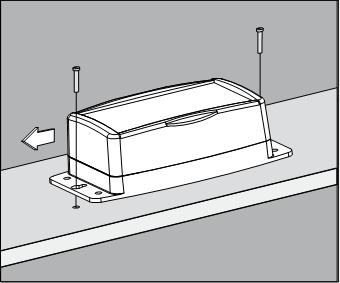
Figure 1 – Mounting the SMS100
2.5 Connecting the SMS100
2.5.1 NMEA 2000® Connection
The NMEA 2000® connector can be found on the side of the enclosure. The NMEA 2000® connector is a round five pin male connector (see Figure 2). You connect the SMS100 to an NMEA 2000® network using a Maretron NMEA 2000® cable (or an NMEA 2000® compatible cable) by connecting the female end of the cable to the SMS100 (note the key on the male connector and keyway on the female connector). Be sure the cable is connected securely and that the collar on the cable connector is tightened firmly. Connect the other end of the cable (male) to the NMEA 2000® network in the same manner. The SMS100 is designed such that you can plug or unplug it from an NMEA 2000® network while the power to the network is connected or disconnected. Please follow recommended practices for installing NMEA 2000® network products.
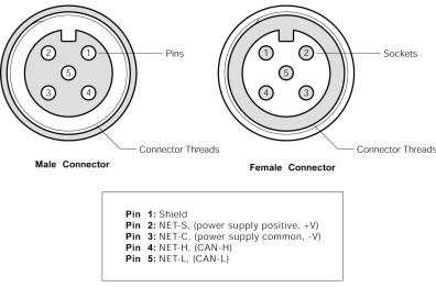
Figure 2 – NMEA 2000® Connector Face Views
2.5.2 Cellular Antenna Connection
The SMS100 has one external SMA cellular antenna connector. This connector is intended for use only with the included TG.10.0113 cellular antenna. Screw the antenna onto the SMA connector and tighten until snug. Rotate the antenna so that it is a vertical orientation for best signal reception.
3 Configuring the SMS100
The SMS100 has several configurable parameters, which are shown below including the default values. If you are not using the default values, then you will need to refer to the corresponding section for configuring the SMS100 appropriately. You may configure the SMS100 using a Maretron DSM150 or DSM250 display or Maretron N2KAnalyzer® software.
3.1 Advanced Configuration
3.1.1 Device Instance
Program this parameter to the desired instance number for this device. You can program this parameter to any value between 0 and 252. The default device instance is 0
3.1.2 Installation Description
This entry allows you to modify the NMEA 2000® installation description text strings. You can enter any information you like here, such as the date the unit was installed, or the location in which it was installed, for later reference. Tools such as Maretron N2KAnalyzer® allow you to view these values later. The default installation description is blank text.
3.1.3 Restore Factory Defaults
This option restores all settings on the SMS100 device to their factory default states.
3.2 Label
Program this parameter with a text string which identifies this device. Maretron display products will display this label text when you are selecting data to display. The default device label is blank.
4 Usage
4.1 Transmitting Messages
The SMS100 may be used to transmit SMS text messages to user-selected telephone numbers on the occurrence of an alert generated by N2KView software (with the optional Alerts license) or the DSM150 or DSM250 displays. Please refer to the N2KView User’s Manual, DSM150 User’s Manual, or DSM250 User’s Manual, as appropriate, for details.
4.2 Receiving Messages
You may send a message to the SMS100 in order to receive a predefined message showing the current status of various parameters on the vessel.
Send a SMS message containing the single word “STATUS” to the telephone number of the SMS100.
The SMS100 will respond with a text message containing the following information:
1) Position
2) Bilge Water Detector Status
3) Battery Voltage
4) AC Voltage
5) Apparent Wind Speed
6) Outdoor Temperature
7) Indoor Temperature
4.3 Monitoring the SMS100
The state of the SMS100’s connection to the cellular network may be observed using N2KView software or the DSM150 or DSM250 displays. Please refer to the N2KView User’s Manual, DSM150 User’s Manual, or DSM250 User’s Manual, as appropriate, for details. From these devices and software, you can observe the following information:
1) Cellular Carrier
2) Telephone number of the SMS100
3) Signal Strength
5 Maintenance
Regular maintenance is not required; however, an occasional inspection will ensure continued proper operation of the Maretron SMS100. Perform the following tasks periodically:
- Clean the unit with a soft cloth. Do not use chemical cleaners as they may remove paint or markings or may corrode the SMS100 enclosure or seals. Do not use any cleaners containing acetone, as they will deteriorate the plastic enclosure.
- Ensure that the unit is mounted securely and cannot be moved relative to the mounting surface. If the unit is loose, tighten the mounting screws.
- Check the security of all cable connections and tighten if necessary.
6 Troubleshooting
If you notice unexpected operation of the Maretron SMS100, follow the troubleshooting procedures in this section to remedy simple problems.
Symptom |
Troubleshooting Procedure |
|
Text Messages not Transmitted |
· Check the connection to the NMEA 2000® and connector and tighten if necessary · Ensure that power is supplied to the connected NMEA 2000® network segment · Use N2KView®, a DSM150, or DSM250 to verify Cellular Provider, signal strength, and active SIM card status · Check that the proper cellular telephone number has been programmed into N2KView®, the DSM150, or DSM250 |
|
No Cellular Provider Indicated |
· Check that the antenna is connected properly to the antenna connector on the SMS100 · Check to see if you are within the coverage area of the cellular operator whose SIM card is installed in the SMS100 · Check that the SIM card has an active SMS plan |
|
SIM Card Not Ready or Present |
· Check that the SIM card is properly installed in the SMS100 · Check that the SIM card has an active SMS plan |
Figure 3 – Troubleshooting Guide
If these steps do not solve your problem, please contact Maretron Technical Support (refer to Section 8 for contact information).
7 Technical Specifications
Specifications
|
Parameter |
Value |
Comment |
|
NMEA 2000® Connector |
DeviceNet Micro-C |
Industry Standard Waterproof |
|
NMEA 2000® Isolation |
Opto-Isolated |
|
|
Antenna Connector |
SMA |
For use only with supplied cellular antenna |
|
Cellular Technologies |
2G GSM/GPRS/EDGE |
|
|
Supported Bands |
800/850/900/1700/ 1900/2100 MHz |
|
Certifications
|
Parameter |
Comment |
|
NMEA 2000® Standard |
Level A |
|
Maritime Navigation and Radiocommunication Equipment & Systems |
IEC 61162-3 |
|
Maritime Navigation and Radiocommunication Equipment & Systems |
IEC 60945 |
|
FCC and R&TTE/CE Mark |
Electromagnetic Compatibility |
|
PTCRB |
Certified |
|
AT&T |
Network Ready |
NMEA 2000® Parameter Group Numbers (PGNs)
|
Description |
PGN # |
PGN Name |
Default Rate |
|
Response to Requested PGNs |
126464 |
PGN List (Transmit and Receive) |
N/A |
|
126996 |
Product Information |
N/A |
|
|
126998 |
Configuration Information |
N/A |
|
|
Protocol PGNs |
059392 |
ISO Acknowledge |
N/A |
|
059904 |
ISO Request |
N/A |
|
|
060416 |
ISO Transport Protocol, Connection Management |
N/A |
|
|
060160 |
ISO Transport Protocol, Data Transfer |
N/A |
|
|
060928 |
ISO Address Claim |
N/A |
|
|
065240 |
ISO Address Command |
N/A |
|
|
126208 |
NMEA Request/Command/Acknowledge |
N/A |
|
|
Periodic PGNs |
130834 |
SMS Status (Maretron Proprietary) |
10 seconds |
|
130835 |
SMS Text Message (Maretron Proprietary) |
On Receipt |
Electrical
|
Parameter |
Value |
Comment |
|
Operating Voltage |
9 to 32 Volts |
DC Voltage |
|
Power Consumption |
<150mA |
Average Current Drain |
|
Load Equivalence Number (LEN) |
3 |
NMEA 2000® Spec. (1LEN = 50 mA) |
|
Reverse Battery Protection |
Yes |
Indefinitely |
|
Load Dump Protection |
Yes |
Energy Rated per SAE J1113 |
Mechanical
|
Parameter |
Value |
Comment |
|
Size |
6.871” x 3.571” x 2.045” (152mm x 91mm x 52 mm) |
Including Flanges for Mounting |
|
Weight |
10.6 oz. (301 g) |
|
Environmental
|
Parameter |
Value |
|
IEC 60945 Classification |
Exposed |
|
Degree of Protection |
IP65 |
|
Operating Temperature |
-25°C to 55°C |
|
Storage Temperature |
-40°C to 85°C |
|
Relative Humidity |
93%RH @40° per IEC60945-8.2 |
|
Vibration |
2-13.2Hz @ ±1mm, 13.2-100Hz @ 7m/s2 per IEC 60945-8.7 |
|
Rain and Spray |
12.5mm Nozzle @ 100liters/min from 3m for 30min per IEC 60945-8.8 |
|
Solar Radiation |
Ultraviolet B, A, Visible, and Infrared per IEC 60945-8.10 |
|
Corrosion (Salt Mist) |
4 times 7days @ 40°C, 95%RH after 2 hour Salt Spray Per IEC 60945-8.12 |
|
Electromagnetic Immunity |
Conducted, Radiated, Fast Transient, Supply, and ESD per IEC 60945-10 |
|
Safety Precautions |
Dangerous Voltage, Electromagnetic Radio Frequency per IEC 60945-12 |
8 Regulatory Compliance
8.1 FCC
This device complies with part 15 of the FCC Rules. Operation is subject to the following two conditions: (1) This device may not cause harmful interference, and (2) this device must accept any interference received, including interference that may cause undesired operation.
CONTAINS FCC ID: XPYLISAU200
9 Technical Support
If you require technical support for Maretron products, you can reach us in any of the following ways:
Telephone: 1-866-550-9100
Fax: 1-602-861-1777
E-mail: [email protected]
World Wide Web: http://www.maretron.com
Mail: Maretron,
LLP
Attn:
Technical Support
9014 N.
23rd Ave Suite 10
Phoenix,
AZ 85021 USA
10 Installation Template
Please check the dimensions before using the following diagram as a template for drilling the mounting holes because the printing process may have distorted the dimensions.
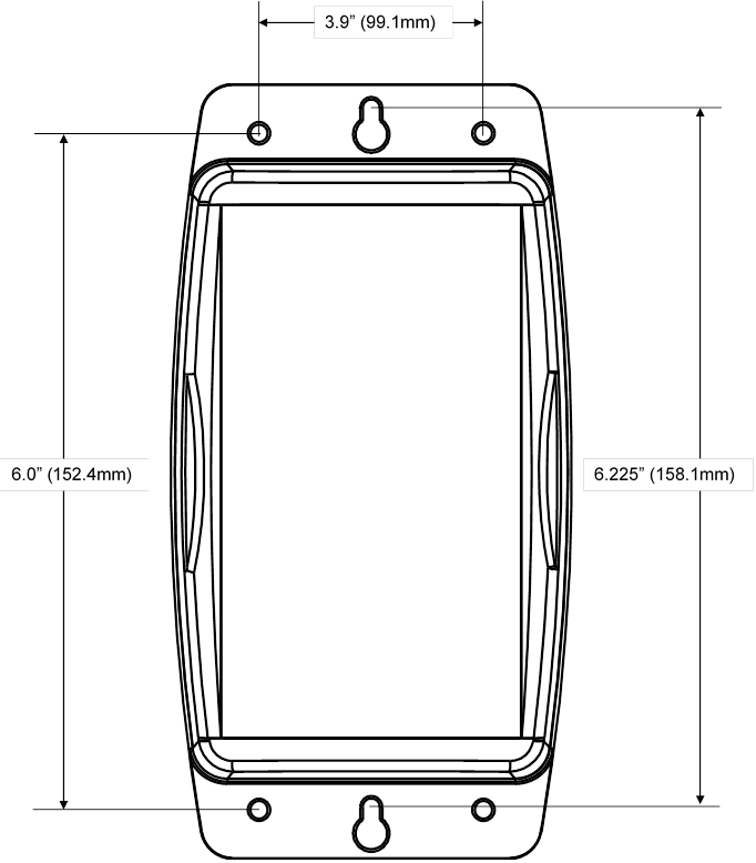
Figure 4
– Mounting Template
11 Maretron (2 Year) Limited Warranty
Maretron warrants the SMS100 to be free from defects in materials and workmanship for two (2) years from the date of original purchase. If within the applicable period any such products shall be proved to Maretron’s satisfaction to fail to meet the above limited warranty, such products shall be repaired or replaced at Maretron’s option. Purchaser's exclusive remedy and Maretron’s sole obligation hereunder, provided product is returned pursuant to the return requirements below, shall be limited to the repair or replacement, at Maretron’s option, of any product not meeting the above limited warranty and which is returned to Maretron; or if Maretron is unable to deliver a replacement that is free from defects in materials or workmanship, Purchaser’s payment for such product will be refunded. Maretron assumes no liability whatsoever for expenses of removing any defective product or part or for installing the repaired product or part or a replacement therefore or for any loss or damage to equipment in connection with which Maretron’s products or parts shall be used. With respect to products not manufactured by Maretron, Maretron’s warranty obligation shall in all respects conform to and be limited to the warranty actually extended to Maretron by its supplier. The foregoing warranties shall not apply with respect to products subjected to negligence, misuse, misapplication, accident, damages by circumstances beyond Maretron’s control, to improper installation, operation, maintenance, or storage, or to other than normal use or service.
THE FOREGOING WARRANTIES ARE EXPRESSLY IN LIEU OF AND EXCLUDES ALL OTHER EXPRESS OR IMPLIED WARRANTIES, INCLUDING BUT NOT LIMITED TO THE IMPLIED WARRANTIES OF MERCHANTABILITY AND OF FITNESS FOR A PARTICULAR PURPOSE.
Statements made by any person, including representatives of Maretron, which are inconsistent or in conflict with the terms of this Limited Warranty, shall not be binding upon Maretron unless reduced to writing and approved by an officer of Maretron.
IN NO CASE WILL MARETRON BE LIABLE FOR INCIDENTAL OR CONSEQUENTIAL DAMAGES, DAMAGES FOR LOSS OF USE, LOSS OF ANTICIPATED PROFITS OR SAVINGS, OR ANY OTHER LOSS INCURRED BECAUSE OF INTERRUPTION OF SERVICE. IN NO EVENT SHALL MARETRON’S AGGREGATE LIABILITY EXCEED THE PURCHASE PRICE OF THE PRODUCT(S) INVOLVED. MARETRON SHALL NOT BE SUBJECT TO ANY OTHER OBLIGATIONS OR LIABILITIES, WHETHER ARISING OUT OF BREACH OF CONTRACT OR WARRANTY, TORT (INCLUDING NEGLIGENCE), OR OTHER THEORIES OF LAW WITH RESPECT TO PRODUCTS SOLD OR SERVICES RENDERED BY MARETRON, OR ANY UNDERTAKINGS, ACTS OR OMISSIONS RELATING THERETO.
Maretron does not warrant that the functions contained in any software programs or products will meet purchaser’s requirements or that the operation of the software programs or products will be uninterrupted or error free. Purchaser assumes responsibility for the selection of the software programs or products to achieve the intended results, and for the installation, use and results obtained from said programs or products. No specifications, samples, descriptions, or illustrations provided Maretron to Purchaser, whether directly, in trade literature, brochures or other documentation shall be construed as warranties of any kind, and any failure to conform with such specifications, samples, descriptions, or illustrations shall not constitute any breach of Maretron’s limited warranty.
Warranty Return Procedure:
To apply for warranty claims, contact Maretron or one of its dealers to describe the problem and determine the appropriate course of action. If a return is necessary, place the product in its original packaging together with proof of purchase and send to an Authorized Maretron Service Location. You are responsible for all shipping and insurance charges. Maretron will return the replaced or repaired product with all shipping and handling prepaid except for requests requiring expedited shipping (i.e. overnight shipments). Failure to follow this warranty return procedure could result in the product’s warranty becoming null and void.
Maretron reserves the right to modify or replace, at its sole discretion, without prior notification, the warranty listed above. To obtain a copy of the then current warranty policy, please go to the following web page: