1 General
1.1 Introduction
Congratulations on your purchase of the Maretron MBB300C Vessel Monitoring and Control Black Box. Maretron has designed and built your system to the highest standards for years of dependable and accurate service.
Maretron’s Black Box (MBB300C) is a dedicated processing unit that includes Maretron’s N2KView® vessel monitoring and control software. Unlike a PC that allows any software to be loaded, the MBB300C runs only N2KView® software, making it extremely stable and dedicated to monitoring and controlling your vessel.
The MBB300C is ruggedized for marine use and includes a solid state disk drive to withstand the pounding associated with waves. And since the MBB300C dissipates less than 10 watts, there is no need for internal cooling fans that are noisy and wear out causing electronics to overheat and fail.
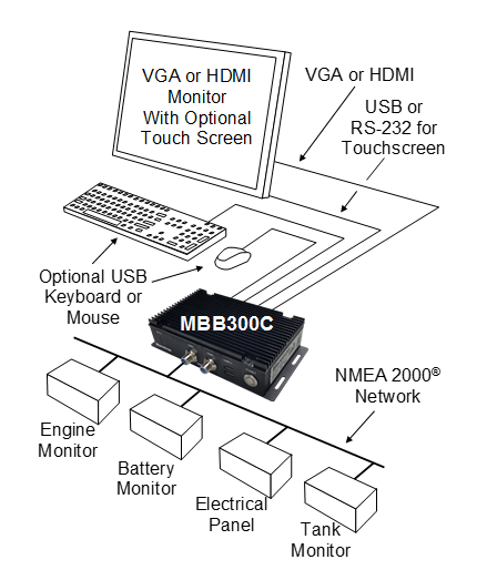
Figure 1 – MBB300C Network Diagram
The MBB300C connects to a monitor through a VGA or HDMI connector and associated touch screen through a USB or serial port connection.
Alternatives to controlling the N2KView® software through a touch screen include keyboards, mice, or track balls connected through USB. In addition to the two completely isolated CAN bus connectors (M12) for easy connection to single or redundant NMEA 2000® networks, the MBB300C has an Ethernet port for connecting Internet Protocol (IP) cameras for viewing within the N2KView® software.
Of course, you get the same flexibility using Maretron’s N2KView® software from the MBB300C as you would running the software on a PC, which includes the ability to configure as many screens as you want with exactly the information you want to see. Plus, you get free upgrades to the software as improvements and new features are added.
The Maretron MBB300C is designed to operate within the harsh demands of the marine environment. However, no piece of marine electronic equipment can function properly unless installed, configured, and maintained in the correct manner. Please read carefully and follow these instructions for installation, configuration, and usage of the Maretron MBB300C in order to ensure optimal performance.
1.2 Firmware Revision
This manual corresponds to the MBB300C running N2KView® Version 5.0.15.
1.3 MBB300C Features
The Maretron MBB300C has the following features.
· Full version of N2KView® software preinstalled
· Wired Ethernet interface
· Dual Optically-Isolated CAN bus connectors for direct NMEA 2000® connection
· Supports user-supplied VGA or HDMI monitor
· Supports user-supplied touchscreen (ELO, 3M Microtouch, Hampshire TSharc, Penmount, General Touch, or any USBHID compliant touchscreen)
· Supports user-supplied mouse and keyboard
· Operates on 9-36VDC
· 10W power consumption
· Solid State Disk Drive
· Fanless cooling system
· All N2KView licenses included
1.4 Quick Install
Installing the Maretron MBB300C display involves the following four steps. Please refer to the individual sections for additional details.
· Unpacking the Box (Section 2.1)
· Choosing a Mounting Location (Section 2.2)
· Mounting the MBB300C (Section 2.3)
· Connecting the MBB300C (Section 2.4)
· Configuring the MBB300C (Section 2.5)
2 Installation
2.1 Unpacking the Box
When unpacking the box containing the Maretron MBB300C, you should find the following items:
· 1 – MBB300C Maretron Vessel Monitoring and Control Black Box
· 1 – 3-Pin Power Connector
· 1 – USB Flash Drive Containing System Documentation
· 1 – Warranty Registration Card
If any of these items are missing or damaged, please contact Maretron.
2.2 Choosing a Mounting Location
The MBB300C must be mounted in an indoor location.
2.3 Mounting the MBB300C
The MBB300C can be mounted to a wall or other flat surface.
2.3.1 Mounting the System
To mount the MBB300C onto a wall or some other surface, please follow the steps below.
Step 1: Turn the MBB300C over.
Step 2: Drill holes in the intended installation surface.
Step 3: Align the mounting holes in the sides of the MBB300C with the predrilled holes in the mounting surface.
Step 4: Insert four retention screws, two on each side, to secure the MBB300C to the wall.
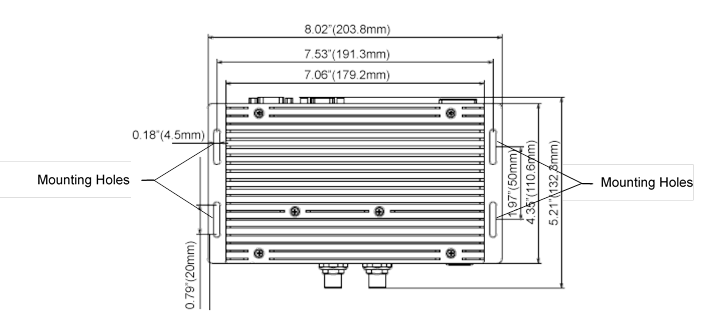
Figure 2 – Mounting Screw Hole Locations
2.4 Connecting the MBB300C
Some I/O interface connections of the MBB300C are found on the front panel (see Figure 3). The I/O interface panel located on the front of the MBB300C has the following I/O interface connectors:
· 2 x CAN-bus ports with isolation for connection to NMEA 2000®
· 2 x SATA HDD LED indicators
· 1 x Power Button with Power LED Indicator
· 2 x USB 2.0 connectors
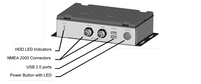
Figure 3 – MBB300C Front Panel Connections
7
The I/O interface panel located on the rear of the MBB300C (see Figure 4) has the following interface connectors:
· 1 x VGA output
· 1 x HDMI output
· 1 x RS-232 Serial Port
· 2 x USB 3.0 connectors
· 1 x Gigabit Ethernet (LAN) port
· 1 x 3-pin power terminal block with wide range power input (9V-36V)
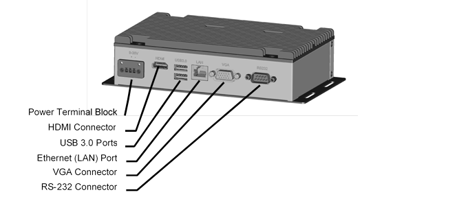
Figure 4 – MBB300C Front Panel
2.4.1 RS-232 Connection
There is one external RS-232 connector. The RS-232 connector enables connection to an external touch screen. To connect a serial cable with the RS-232 connector, please follow the instructions below.
Step 1: Locate the RS-232 connector on the rear panel of the MBB300C.
Step 2: Align the RS-232 connector on the serial cable with the RS-232 connector on the rear panel of the MBB300C.
Step 3: Once aligned, gently insert the serial cable RS-232 connector into the MBB300C RS-232 connector.
2.4.2 Video Connection
|
|
NOTE
|

2.4.2.1 VGA Connection
There is one external VGA connector. The VGA connector enables connection to a monitor. To connect a VGA cable with the VGA connector, please follow the instructions below.
Step 1: Locate the VGA connector on the rear panel of the MBB300C.
Step 2: Align the VGA connector on the cable with the VGA connector on the rear panel of the MBB300C.
Step 3: Once aligned, gently insert the cable VGA connector into the MBB300C VGA connector.
2.4.2.2 HDMI Connection
There is one external HDMI connector. The HDMI connector enables connection to a monitor. To connect a HDMI cable with the HDMI connector, please follow the instructions below.
Step 1: Locate the HDMI connector on the rear panel of the MBB300C.
Step 2: Align the HDMI connector on the cable with the HDMI connector on the rear panel of the MBB300C.
Step 3: Once aligned, gently insert the cable HDMI connector into the MBB300C HDMI connector.
2.4.3 LAN Connection
There is one external RJ-45 LAN connector. The RJ-45 connector enables connection to an external network. To connect a LAN cable with the RJ-45 connector, please follow the instructions below.
Step 1: Locate the RJ-45 connector on the rear panel of the MBB300C.
Step 2: Align the RJ-45 connector on the LAN cable with the RJ-45 connector on the rear panel of the MBB300C (see Figure 5).

Figure 5 – LAN Connection
Step 3: Once aligned, gently insert the LAN cable RJ-45 connector into the onboard RJ-45 connector.
2.4.4 USB Device Connection
There are two external USB 2.0 connectors and two external USB 3.0 connectors. To connect a USB device, please follow the instructions below.
Step 1: The locations of the USB connectors are shown in Figure 3 and Figure 4.
Step 2: Align the USB device connector with one of the connectors (see Figure 6).
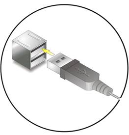
Figure 6 – USB Device Connection
Step 3: Once aligned, gently insert the USB device connector into the MBB300C connector.
2.4.5 Power Connection
The MBB300C can be connected to a power source in the following way (overcurrent protection should be provided and should be sized in accordance with ABYC E-11, AC and DC ELECTRICAL SYSTEMS ON BOATS):
Directly with 9-36VDC power source using the green power terminal block found on the rear panel of the MBB300C (see Figure 7).
a) Connect the power source negative terminal to the right hand terminal,
b) Connect the power source positive terminal to the center terminal.

Figure 7 – MBB300C Power Terminal Block
2.4.6 Power Sequencing
When the MBB300C is connected to an appropriate power source, you can use the power switch located on the front panel (see Figure 4) to turn the MBB300C on or off. The MBB300C can also be switched on and off by applying or removing power through an external switch or breaker. Any time the power is reapplied to the MBB300C, it will turn on.
2.5 Configuring the MBB300C
In order to use the MBB300C, you must have it connected to the NMEA 2000® network.
The MBB300C will start up with the following warning screen:
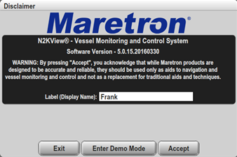
Figure 8 – MBB300C Startup Screen
The first time you start the MBB300C, N2KView® will ask you to assign it a unique name. Assigning a unique name to the MBB300C is necessary in order to help you determine the source of alerts generated by a MBB300C or other Maretron device capable of generating alerts.
You are required to press Accept and thereby acknowledge this warning message before N2KView® will run in Live Mode.
Alternatively, you may Enter Demo Mode. In Demo Mode, you will not be able to connect to an NMEA 2000® network and view live data; instead, simulated data will be provided to stimulate the controls.
Finally, you may choose Exit, in which case the MBB300C will power off.
2.5.1 Manually Entering LAN Connection Information
|
|
NOTE
The LAN Connection is not necessary unless you are using any of the following features:
|

If you intend to use the Video feature or send e-mails via the Alerts feature, you must ensure that the device can connect to your LAN (local area network). The MBB300C comes from the factory preconfigured to obtain its LAN connection information from a DHCP (Dynamic Host Control Protocol) server. If your local area network uses a DHCP server, no configuration is necessary, and the MBB300C should be able to successfully connect to the local area network.
If your local area network does not use DHCP, you must manually enter the LAN connection information into the MBB300C. This is done through the following steps:
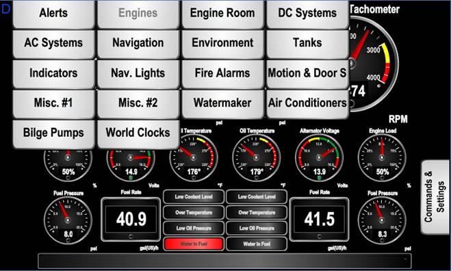
Figure 9 – N2KView® Window with Tabs Displayed
a. Click anywhere inside the N2KView® screen to display the screen tabs as shown in Figure 9 above.
b. Click on the “Commands & Settings” tab (on the right) to display the Commands & Settings Dialog.
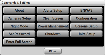
Figure 10 – Commands and Settings Dialog
c. Click on the “Configuration” button in the Commands & Settings window to display the Configuration dialog.
d. Click on the “Network Configuration” tab in the Configuration dialog to display the Network Configuration dialog.
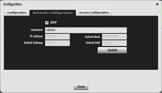
Figure 11 – Configuration Dialog
e. Uncheck the “DHCP” box to indicate that your LAN does not use DHCP.
f. In the “IP Address” field, enter the IP address you wish to assign to the MBB300C.
g Click on the “Configuration” button in the Commands & Settings window to display the Configuration dialog.
h. In the “Subnet Mask” field, enter the subnet mask value used on your LAN (in most cases, this value will be “255.255.255.0”).
i. In the “Default Gateway” field, enter the IP address of the default gateway of your LAN.
j. In the “Default DNS” field, enter the IP address of a DNS (Dynamic Name Service) Server used on your LAN.
k. Click the “Update” button to make these changes permanent. The screen will go blank for a few seconds while this is being done.
3 Operating the MBB300C
3.1 Turning the MBB300C On
To turn on the MBB300C, press the power switch, located on the right hand side of the front panel of the MBB300C. The power button LED will illuminate.
3.2 Turning the MBB300C Off
To turn the MBB300C off, use the “Shutdown” administrative tab of the N2KView® software. Alternatively, you can power down the unit by pressing the MBB300C’s power switch. Lastly, you can power down the unit by turning off the power source with an external breaker or external switch. The power button LED will turn off after the shutoff process has completed.
3.3 Using the MBB300C
The MBB300C runs a fully functional version of the Maretron N2KView® software. Please refer to the N2KView® User’s Manual, packaged with the MBB300C, for detailed operating instructions.
4 Maintenance
Regular maintenance is important to ensure continued proper operation of the Maretron MBB300C. Perform the following tasks periodically:
· Clean the unit with a soft cloth. Do not use chemical cleaners as they may remove paint or markings or may corrode the MBB300C enclosure or seals. Do not use any cleaners containing acetone, as they will deteriorate the plastic enclosure. Do not spray cleaning liquids directly onto the MBB300C.
· Ensure that the unit is mounted securely and cannot be moved relative to the mounting surface. If the unit is loose, tighten the mounting screws.
· Check the security of the power and network cables connected to the MBB300C and tighten if necessary.
5 Troubleshooting
If you notice unexpected operation of the Maretron MBB300C, follow the troubleshooting procedures in this section to remedy simple problems.
|
Symptom |
Troubleshooting Procedure |
|
No activity on the display |
Check the connection to the power and network connectors and tighten if necessary Ensure that power is supplied to the connected power cable. Check the connection to the power jack located on the rear of the device. Press the power switch located on the front of the device on the right-hand side. Check that the NMEA 2000® interfaces are correctly connected to the NMEA 2000® network. |
|
Other Issues |
Please refer to the Troubleshooting section of the N2KView® User’s Manual. |
If these steps do not solve your problem, please contact Maretron Technical Support (refer to Section Technical Support for contact information).
Warning: There are no user-serviceable components inside the Maretron MBB300C. Opening the MBB300C will expose the sensitive electronic components to adverse environmental conditions that may render the unit inoperative. Please do not open the MBB300C, as this will automatically void the warranty. If service is required, please return the unit to an authorized Maretron service location.
6 Technical Specifications
Specifications
|
Parameter |
Value |
Comment |
|
Video Connector |
VGA Port HDMI Port |
For Monitor Connection |
|
Monitor Resolution |
2560 × 1600 Maximum (VGA) 1920 × 1080 Maximum (HDMI) |
|
|
USB Connector |
Two USB 3.0 connections Two USB 2.0 connections |
For connecting Peripherals (Mouse, keyboard, etc.) and or touch screen connectivity |
|
Serial Connector |
One RS232 9-Pin D Connector |
For touch screen alternative connection |
|
Touchscreen Drivers |
TSHARC, 3M MicroTouch, ELO, eGalax, General Touch |
Compatible with HID touch compliant panels |
|
Ethernet Connector |
RJ-45 GbE |
For connection to IP cameras |
|
Controller Area Network (CAN) Ports |
Two NMEA 2000 Micro-C Connectors |
|
Certifications
|
Parameter |
Comment |
|
FCC class A and CE Mark |
Electromagnetic Compatibility |
|
NMEA 2000® |
|
Electrical
|
Parameter |
Value |
Comment |
|
Operating Voltage (Dedicated Supply Connection) |
9–36 Volts |
DC Voltage |
|
Power Consumption (Dedicated Supply Connection) |
10 Watts |
Maximum |
|
Operating Voltage (NMEA 2000® Connection) |
8–32 Volts |
DC Voltage |
|
Power Consumption (NMEA 2000® Connection) |
80 mA |
Maximum When Transmitting 100% |
|
Load Equivalence Number (LEN) |
1 |
NMEA 2000® Spec. (1 LEN = 50 mA) |
|
Reverse Battery Protection (NMEA 2000® Connection) |
Yes |
Indefinitely |
|
Load Dump Protection (NMEA 2000® Connection) |
Yes |
Energy Rated per SAE J1113 |
Mechanical
|
Parameter |
Value |
Comment |
|
Overall Dimensions (D×W×H) |
6.02” × 9.76” × 1.73” (132 mm x 204 mm x 49 mm) |
Excluding Connectors and Wall Brackets |
|
Weight |
2.27 lbs (1.03 kg) |
|
|
Chassis Material |
Aluminum |
|
|
Mounting |
Wall Bracket |
Any Orientation |
Environmental
|
Parameter |
Value |
|
Operating Temperature |
-20°C to 70°C |
|
Storage Temperature |
-40°C to 85°C |
|
Humidity |
10%–85% RH non-condensing |
7 Technical Support
If you require technical support for Maretron products, you can reach us in any of the following ways:
Fax: 1-602-861-1777
E-mail: [email protected]
World Wide Web: http://www.maretron.com
Mail: Maretron, LLP
Attn: Technical Support
9014 N. 23rd Ave
Suite 10
Phoenix, AZ 85021 USA