1 General
1.1 Introduction
Congratulations on your purchase of the Maretron MBB200C Vessel Monitoring and Control Black Box. Maretron has designed and built your system to the highest standards for years of dependable and accurate service.
Maretron’s Black Box (MBB200C) is a dedicated processing unit that includes Maretron’s N2KView® vessel monitoring and control software. Unlike a PC that allows any software to be loaded, the MBB200C runs only N2KView® software, making it extremely stable and dedicated to monitoring and controlling your vessel.
The MBB200C is ruggedized for marine use and includes a solid state disk drive to withstand the pounding associated with waves. And since the MBB200C dissipates less than 25 watts, there is no need for internal cooling fans that are noisy and wear out causing electronics to overheat and fail.
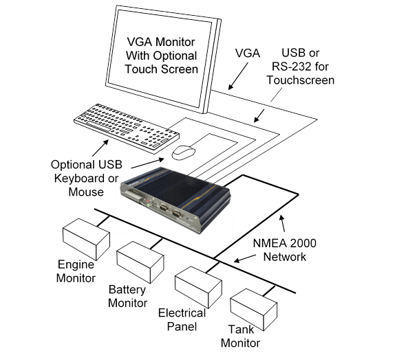
Figure 1 – MBB200C Network Diagram
The MBB200C connects to a monitor through a VGA connector and associated touch screen through a USB or serial port connection. Alternatives to controlling the N2KView® software through a touch screen include keyboards, mice, or track balls connected through USB. In addition to the two completely isolated CAN bus connectors (M12) for easy connection to single or redundant NMEA 2000® networks, the MBB200C has an Ethernet port for connecting Internet Protocol (IP) cameras for viewing within the N2KView® software.
Of course, you get the same flexibility using Maretron’s N2KView® software from the MBB200C as you would running the software on a PC, which includes the ability to configure as many screens as you want with exactly the information you want to see. Plus, you get free upgrades to the software as improvements and new features are added.
The Maretron MBB200C is designed to operate within the harsh demands of the marine environment. However, no piece of marine electronic equipment can function properly unless installed, configured, and maintained in the correct manner. Please read carefully and follow these instructions for installation, configuration, and usage of the Maretron MBB200C in order to ensure optimal performance.
1.2 Firmware Revision
This manual corresponds to the MBB200C running N2KView® Version 4.0.2.
1.3 MBB200C Features
|
|
NOTE
Although the MBB200C looks similar to the former MBB100 product, there are important differences. The MBB200C is a standalone NMEA 2000® computer, with the following features:
· The MBB200C includes two CAN interfaces for direct connection to one or two NMEA 2000® networks. · The MBB200C includes all N2KView® capabilities that were formerly licensed separately in the MBB200: Alerts, Control, Fuel Management, and Video. No gateways (such as the IPG100), hardware license keys, or additional software licenses are needed. · You don’t need to connect or configure LAN connections, unless you are using Video or E-mail alert actions. · N2KView® configurations are transferred to and from other N2KView® devices using a USB flash drive plugged into one of the MBB200C’s USB ports. |

The Maretron MBB200C has the following features.
· Full version of N2KView® software preinstalled
· Wired Ethernet interface
· Dual Optically-Isolated CAN bus connectors for direct NMEA 2000® connection
· Supports user-supplied VGA monitor
· Supports user-supplied touchscreen (ELO, 3M Microtouch, Hampshire TSharc, Penmount)
· Supports user-supplied mouse and keyboard
· Supports Bluetooth mice and keyboards with built-in Bluetooth adapter
· Operates on 9-36VDC
· 25W power consumption
· Solid State Disk Drive
· Fanless cooling system
· All N2KView licenses included
1.4 Quick Install
Installing the Maretron MBB200C display involves the following four steps. Please refer to the individual sections for additional details.
· Unpacking the Box (Section 2.1)
· Choosing a Mounting Location (Section 2.2)
· Mounting the MBB200C (Section 2.3)
· Connecting the MBB200C (Section 2.4)
· Configuring the MBB200C (Section 2.5)
2 Installation
2.1 Unpacking the Box
When unpacking the box containing the Maretron MBB200C, you should find the following items:
· 1 – MBB200C Maretron Vessel Monitoring and Control Black Box
· 1 – NMEA 2000® adapter cable
· 2 – Mounting Brackets
· 1 – Short Screw Set (Used for Mounting Bracket)
· 1 – AC Power Cord
· 1 – AC Power Supply
· 1 – Rubber Feet/Long Screw Set
· 1 – MBB200C User’s Manual
· 1 – N2KView® Documentation CD-ROM
· 1 – Warranty Registration Card
If any of these items are missing or damaged, please contact Maretron.
2.2 Choosing a Mounting Location
The MBB200C must be mounted in an indoor location.
2.3 Mounting the MBB200C
The MBB200C can be mounted to a wall or other flat surface with the included mounting brackets.
2.3.1 Mounting the System with Mounting Brackets
To mount the MBB200C onto a wall or some other surface using the two mounting brackets, please follow the steps below.
Step 1: Turn the MBB200C over.
Step 2: Align the two retention screw holes in each bracket with the corresponding retention screw holes on the sides of the MBB200C bottom surface (marked in red in Figure 2).
Step 3: Secure the brackets to the MBB200C by inserting two retention screws into each bracket.
Step 4: Drill holes in the intended installation surface.
Step 5: Align the mounting holes in the sides of the mounting brackets with the predrilled holes in the mounting surface.
Step 6: Insert four retention screws, two in each bracket, to secure the MBB200C to the wall.
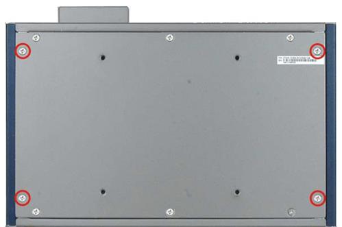
Figure 2 – Mounting Bracket Screw Hole Locations
2.4 Connecting the MBB200C
Most I/O interface connections of the MBB200C are found on the front panel (see Figure 3). The I/O interface panel located on the front of the MBB200C has the following I/O interface connectors:
· 2 x CAN-bus ports with isolation for connection to NMEA 2000®
· 1 x CompactFlash® Card Socket
· 1 x HDD LED indicator
· 1 x Audio line-out jack (green)
· 1 x Mic-in port (pink)
· 1 x Power LED Indicator
· 1 x Reset button
· 2 x USB 2.0 connectors
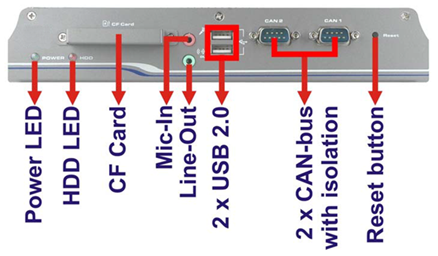
Figure 3 – MBB200C Front Panel Connections
The I/O interface panel located on the rear of the MBB200C (see Figure 4) has the following interface connectors:
· 1 x VGA output
· 1 x RS-232 Serial Port
· 2 x USB port connectors
· 1 x Gigabit Ethernet (LAN) port
· 1 x 12V DC power jack
· 1 x 3-pin power terminal block with wide range power input (9V-36V)
· 1 x power switch
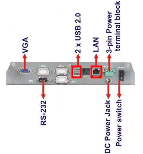
Figure 4 – MBB200C Front Panel
2.4.1 RS-232 Connection
There is one external RS-232 connector. The RS-232 connector enables connection to an external touch screen. To connect a serial cable with the RS-232 connector, please follow the instructions below.
Step 1: Locate the RS-232 connector on the rear panel of the MBB200C.
Step 2: Align the RS-232 connector on the serial cable with the RS-232 connector on the rear panel of the MBB200C.
Step 3: Once aligned, gently insert the serial cable RS-232 connector into the MBB200C RS-232 connector.
2.4.2 VGA Connection
There is one external VGA connector. The VGA connector enables connection to a monitor. To connect a VGA cable with the VGA connector, please follow the instructions below.
Step 1: Locate the VGA connector on the rear panel of the MBB200C.
Step 2: Align the VGA connector on the cable with the VGA connector on the rear panel of the MBB200C.
Step 3: Once aligned, gently insert the cable VGA connector into the MBB200C VGA connector.
2.4.3 LAN Connection
There is one external RJ-45 LAN connector. The RJ-45 connector enables connection to an external network. To connect a LAN cable with the RJ-45 connector, please follow the instructions below.
Step 1: Locate the RJ-45 connector on the rear panel of the MBB200C.
Step 2: Align the RJ-45 connector on the LAN cable with the RJ-45 connector on the rear panel of the MBB200C (see Figure 5).
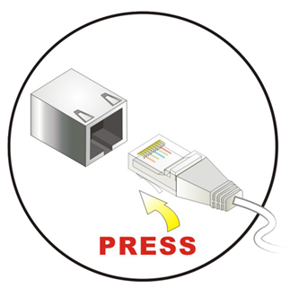
Figure 5 – LAN Connection
Step 3: Once aligned, gently insert the LAN cable RJ-45 connector into the onboard RJ-45 connector.
2.4.4 USB Device Connection
There are four external USB 2.0 connectors. To connect a USB 2.0 or USB 1.1 device, please follow the instructions below.
Step 1: The locations of the USB connectors are shown in Figure 3 and Figure 4.
Step 2: Align the USB device connector with one of the connectors (see Figure 6).
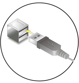
Figure 6 – USB Device Connection
Step 3: Once aligned, gently insert the USB device connector into the MBB200C connector.
2.4.5 Power Connection
The MBB200C can be connected to a power source in one of two ways (overcurrent protection should be provided and should be sized in accordance with ABYC E-11, AC and DC ELECTRICAL SYSTEMS ON BOATS);
1) Directly with 9-32VDC power source using the green power terminal block found on the rear panel of the MBB200C (see Figure 7).
a) Connect the power source negative terminal to the right hand terminal,
b) Connect the power source positive terminal to the center terminal.
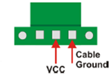
Figure 7 – MBB200C Power Terminal Block
2) Indirectly with 100-240VAC 47-63Hz power source using the AC power adapter and the AC power cord supplied in the box.
a) Connect the AC power cord to the AC power adapter,
b) Connect the AC power cord to the AC power outlet,
c) Connect the 12VDC connector from the AC power adapter to the MBB200C’s 12VDC power input connector.
2.4.6 Power Sequencing
When the MBB200C is connected to an appropriate power source, you can use the power switch located on the front panel (see Figure 4) to turn the MBB200C on or off. The MBB200C can also be switched on and off by applying or removing power through an external switch or breaker. Any time the power is reapplied to the MBB200C, it will turn on.
2.5 Configuring the MBB200C
In order to use the MBB200C, you must have it connected to the NMEA 2000® network.
The MBB200C will start up with the following warning screen:
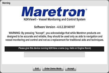
Figure 8 – MBB200C Startup Screen
The first time you start the MBB200C, N2KView® will ask you to assign it a unique name. Assigning a unique name to the MBB200C is necessary in order to help you determine the source of alerts generated by a MBB200C or other Maretron device capable of generating alerts.
You are required to press Accept and thereby acknowledge this warning message before N2KView® will run in Live Mode.
Alternatively, you may Enter Demo Mode. In Demo Mode, you will not be able to connect to an NMEA 2000® network and view live data; instead, simulated data will be provided to stimulate the controls.
Finally, you may choose Exit, in which case the MBB200C will power off.
2.5.1 Manually Entering LAN Connection Information
|
|
NOTE
The LAN Connection is not necessary unless you are using any of the following features:
|

If you intend to use the Video feature or send e-mails via the Alerts feature, you must ensure that the device can connect to your LAN (local area network). The MBB200C comes from the factory preconfigured to obtain its LAN connection information from a DHCP (Dynamic Host Control Protocol) server. If your local area network uses a DHCP server, no configuration is necessary, and the MBB200C should be able to successfully connect to the local area network.
If your local area network does not use DHCP, you must manually enter the LAN connection information into the MBB200C. This is done through the following steps:
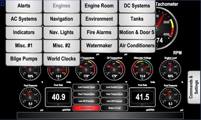
Figure 9 – N2KView® Window with Tabs Displayed
a. Click anywhere inside the N2KView® screen to display the screen tabs as shown in Figure 9 above.
b. Click on the “Commands & Settings” tab (on the right) to display the Commands & Settings Dialog.
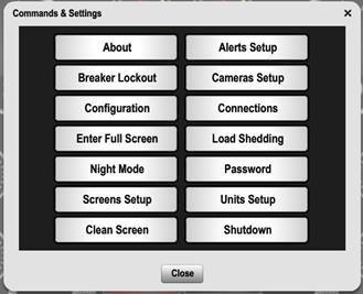
Figure 10 – Commands and Settings Dialog
c. Click on the “Configuration” button in the Commands & Settings window to display the Configuration dialog.
d. Click on the “Network Configuration” tab in the Configuration dialog to display the Network Configuration dialog.
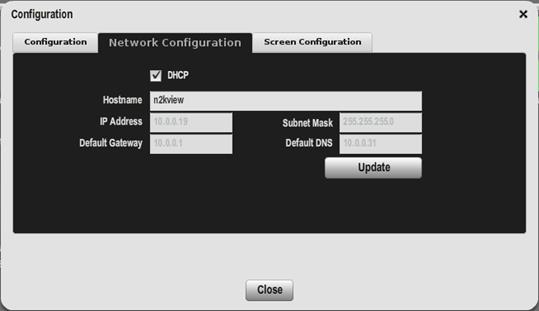
Figure 11 – Configuration Dialog
e. Uncheck the “DHCP” box to indicate that your LAN does not use DHCP.
f. In the “IP Address” field, enter the IP address you wish to assign to the MBB200C.
g Click on the “Configuration” button in the Commands & Settings window to display the Configuration dialog.
h. In the “Subnet Mask” field, enter the subnet mask value used on your LAN (in most cases, this value will be “255.255.255.0”).
i. In the “Default Gateway” field, enter the IP address of the default gateway of your LAN.
j. In the “Default DNS” field, enter the IP address of a DNS (Dynamic Name Service) Server used on your LAN.
k. Click the “Update” button to make these changes permanent. The screen will go blank for a few seconds while this is being done.
3 Operating the MBB200C
3.1 Turning the MBB200C On
To turn on the MBB200C, press the power switch, located on the right hand side of the front panel of the MBB200C.
3.2 Turning the MBB200C Off
To turn the MBB200C off, use the “Shutdown” administrative tab of the N2KView® software. Alternatively, you can power down the unit by pressing the MBB200C’s power switch. Lastly, you can power down the unit by turning off the power source with an external breaker or external switch.
3.3 Using the MBB200C
The MBB200C runs a fully functional version of the Maretron N2KView® software. Please refer to the N2KView® User’s Manual, packaged with the MBB200C, for detailed operating instructions.
4 Maintenance
Regular maintenance is important to ensure continued proper operation of the Maretron MBB200C. Perform the following tasks periodically:
· Clean the unit with a soft cloth. Do not use chemical cleaners as they may remove paint or markings or may corrode the MBB200C enclosure or seals. Do not use any cleaners containing acetone, as they will deteriorate the plastic enclosure. Do not spray cleaning liquids directly onto the MBB200C.
· Ensure that the unit is mounted securely and cannot be moved relative to the mounting surface. If the unit is loose, tighten the mounting screws.
· Check the security of the power and network cables connected to the MBB200C and tighten if necessary.
5 Troubleshooting
If you notice unexpected operation of the Maretron MBB200C, follow the troubleshooting procedures in this section to remedy simple problems.
|
Symptom |
Troubleshooting Procedure |
|
No activity on the display |
Check the connection to the power and network connectors and tighten if necessary Ensure that power is supplied to the connected power cable. Check the connection to the power jack located on the rear of the device. Press the power switch located on the front of the device on the right-hand side. Check that the NMEA 2000® interfaces are correctly connected to the NMEA 2000® network. |
|
Other Issues |
Please refer to the Troubleshooting section of the N2KView® User’s Manual. |
If these steps do not solve your problem, please contact Maretron Technical Support (refer to Section Technical Support for contact information).
Warning: There are no user-serviceable components inside the Maretron MBB200C. Opening the MBB200C will expose the sensitive electronic components to adverse environmental conditions that may render the unit inoperative. Please do not open the MBB200C, as this will automatically void the warranty. If service is required, please return the unit to an authorized Maretron service location.
6 Technical Specifications
|
Parameter |
Value |
Comment |
|
Video Connector |
One VGA Port (RGB or D-sub 15) |
For Monitor Connection |
|
Monitor Resolution |
2048 x 1536 Maximum |
|
|
USB Connector |
Four USB 2.0 connections |
For connecting Peripherals (Mouse, keyboard, etc.) and or touch screen connectivity |
|
Serial Connector |
One RS232 9-Pin D Connector |
For touch screen alternative connection |
|
Touchscreen Drivers |
TSHARC, 3M MicroTouch, ELO, eGalax |
|
|
Ethernet Connector |
One RJ-45 GbE |
For connection to IP Cameras or use for Alert E-mail transmission |
|
Audio Connection |
One Speaker Output |
|
|
Controller Area Network (CAN) Ports |
Two DB-9 Connectors |
One NMEA2000® adapter cable included |
Certifications
|
Parameter |
Comment |
|
FCC class A and CE Mark |
Electromagnetic Compatibility |
|
NMEA 2000® |
|
Electrical
|
Parameter |
Value |
Comment |
|
Operating Voltage (Dedicated Supply Connection) |
9-36 Volts |
DC Voltage |
|
Power Consumption (Dedicated Supply Connection) |
22.2 Watts |
|
|
Operating Voltage (NMEA 2000® Connection) |
8-32 Volts |
DC Voltage |
|
Power Consumption (NMEA 2000® Connection) |
0mA |
|
|
Load Equivalence Number (LEN) |
0 |
NMEA 2000® Spec (1 LEN = 50 mA) |
|
Reverse Battery Protection (NMEA 2000® Connection) |
Yes |
Indefinitely |
|
Load Dump Protection (NMEA 2000® Connection) |
Yes |
Energy Rated per SAE J1110 |
Mechanical
|
Parameter |
Value |
Comment |
|
Overall Dimensions (DxWxH) |
6.02” x 9.76” x 1.73” (153mm x 248mm x 44mm) |
Including Flanges for Mounting |
|
Weight |
4.6 lbs (2.1kg) |
|
|
Chassis Material |
Aluminum |
|
|
Mounting |
VESA 100, Wall Bracket, DIN Rail |
Any Orientation |
Environmental
|
Parameter |
Value |
|
Operating Temperature |
-10°C to 60°C |
|
Operating Shock |
Half-sine wave shock 3G; 11 ms; 3 shocks per axis |
|
Operating Vibration |
MIL-STD-810F 514.5C-2 |
7 Technical Support
If you require technical support for Maretron products, you can reach us in any of the following ways:
Fax: 1-602-861-1777
E-mail: [email protected]
World Wide Web: http://www.maretron.com
Mail: Maretron, LLP
Attn: Technical Support
9014 N. 23rd Ave
Suite 10
Phoenix, AZ 85021 USA
8 Maretron (2 Year) Limited Warranty
Maretron warrants the MBB200C to be free from defects in materials and workmanship for two (2) years from the date of original purchase. If within the applicable period any such products shall be proved to Maretron’s satisfaction to fail to meet the above limited warranty, such products shall be repaired or replaced at Maretron’s option. Purchaser's exclusive remedy and Maretron’s sole obligation hereunder, provided product is returned pursuant to the return requirements below, shall be limited to the repair or replacement, at Maretron’s option, of any product not meeting the above limited warranty and which is returned to Maretron; or if Maretron is unable to deliver a replacement that is free from defects in materials or workmanship, Purchaser’s payment for such product will be refunded. Maretron assumes no liability whatsoever for expenses of removing any defective product or part or for installing the repaired product or part or a replacement therefore or for any loss or damage to equipment in connection with which Maretron’s products or parts shall be used. With respect to products not manufactured by Maretron, Maretron’s warranty obligation shall in all respects conform to and be limited to the warranty actually extended to Maretron by its supplier. The foregoing warranties shall not apply with respect to products subjected to negligence, misuse, misapplication, accident, damages by circumstances beyond Maretron’s control, to improper installation, operation, maintenance, or storage, or to other than normal use or service.
THE FOREGOING WARRANTIES ARE EXPRESSLY IN LIEU OF AND EXCLUDES ALL OTHER EXPRESS OR IMPLIED WARRANTIES, INCLUDING BUT NOT LIMITED TO THE IMPLIED WARRANTIES OF MERCHANTABILITY AND OF FITNESS FOR A PARTICULAR PURPOSE.
Statements made by any person, including representatives of Maretron, which are inconsistent or in conflict with the terms of this Limited Warranty, shall not be binding upon Maretron unless reduced to writing and approved by an officer of Maretron.
IN NO CASE WILL MARETRON BE LIABLE FOR INCIDENTAL OR CONSEQUENTIAL DAMAGES, DAMAGES FOR LOSS OF USE, LOSS OF ANTICIPATED PROFITS OR SAVINGS, OR ANY OTHER LOSS INCURRED BECAUSE OF INTERRUPTION OF SERVICE. IN NO EVENT SHALL MARETRON’S AGGREGATE LIABILITY EXCEED THE PURCHASE PRICE OF THE PRODUCT(S) INVOLVED. MARETRON SHALL NOT BE SUBJECT TO ANY OTHER OBLIGATIONS OR LIABILITIES, WHETHER ARISING OUT OF BREACH OF CONTRACT OR WARRANTY, TORT (INCLUDING NEGLIGENCE), OR OTHER THEORIES OF LAW WITH RESPECT TO PRODUCTS SOLD OR SERVICES RENDERED BY MARETRON, OR ANY UNDERTAKINGS, ACTS OR OMISSIONS RELATING THERETO.
Maretron does not warrant that the functions contained in any software programs or products will meet purchaser’s requirements or that the operation of the software programs or products will be uninterrupted or error free. Purchaser assumes responsibility for the selection of the software programs or products to achieve the intended results, and for the installation, use and results obtained from said programs or products. No specifications, samples, descriptions, or illustrations provided Maretron to Purchaser, whether directly, in trade literature, brochures or other documentation shall be construed as warranties of any kind, and any failure to conform with such specifications, samples, descriptions, or illustrations shall not constitute any breach of Maretron’s limited warranty.
Warranty Return Procedure:
To apply for warranty claims, contact Maretron or one of its dealers to describe the problem and determine the appropriate course of action. If a return is necessary, place the product in its original packaging together with proof of purchase and send to an Authorized Maretron Service Location. You are responsible for all shipping and insurance charges. Maretron will return the replaced or repaired product with all shipping and handling prepaid except for requests requiring expedited shipping (i.e. overnight shipments). Failure to follow this warranty return procedure could result in the product’s warranty becoming null and void.
Maretron reserves the right to modify or replace, at its sole discretion, without prior notification, the warranty listed above. To obtain a copy of the then current warranty policy, please go to the following web page: