Installation Instructions
M1AR, M2AR Fuel Flow Sensors
|
|
WARNING NEVER disassemble the fuel flow sensor. The sensor is factory sealed, and disassembly will void the product warranty. If you feel that the sensor is not functioning correctly, please contact Maretron Technical Support. |
 Operating
Principle
Operating
Principle
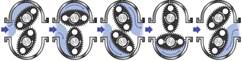
When fluid passes through the sensor, the rotors turn, as shown in the figure on the right. Magnets which are located in the rotors will pass across sensors in the sensor circuit board. Pulses from these sensors are transmitted to the FFM100 which performs flow rate calculations based on the received pulses.
Instructions
Please follow these instructions to connect the M1AR or M2AR fuel flow sensor to the NMEA 2000® network via a Maretron FFM100 Fuel Flow Monitor.
1. The fuel flow sensors are compatible with fuel, lubricating oil, hydraulic fluid, or other clean petroleum based products and should not be used with any other fluid types.
2. The fuel flow sensor contains shafts on which the oval rotors spin. The fuel flow sensor must be mounted so that these rotor shafts are always in a horizontal plane (parallel with the ground or water surface). The rotor shafts are parallel to the four screws attaching the sensor cap to the sensor base, so ensure that these screws are in a horizontal plane. Please refer to Figure 1 below for examples of correct and incorrect orientations.
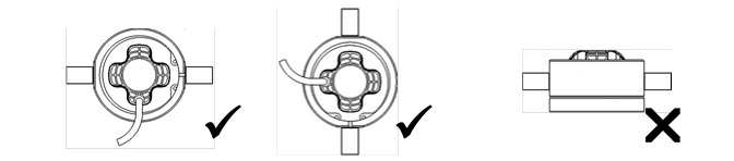
Figure 1 - Correct and Incorrect Mounting Orientations
3. To prevent damage from dirt or foreign matter, it is required that either 1) a diesel fuel filter capable of filtering out 75 micron particles or 2) a Y or basket type 200 mesh strainer be installed as close as possible to the inlet side of the sensor.
4. Install so that the direction of the “FLOW” arrow on the sensor label matches the direction of fuel flow.
5. All M1AR and M2AR fuel flow sensor accessories for the FFM100 are fitted with 1/4” NPT female threads.
6. Use a liquid thread sealant on all pipe threads. Do NOT use Teflon tape. The fittings should be tightened hand tight, then a further 1/2 to 1 turn. Do not over tighten. Systems should always be installed to applicable marine standards.
7. Extreme care must be taken when installing the sensor. Pipe strain or over tightening pipe connections can cause sensor damage.
8. To prevent damage to the sensor from entrapped air during initial commissioning or after maintenance, slowly fill the system with fuel (this will prevent damage caused by air purge). Failure to do this could damage the sensor. NEVER blow or send compressed air through the sensor as this may over rev and damage the sensor.
9. Connect the six wires of the pressure transducer to a free pressure monitoring channel. Please refer to Figure 2 below for details.
10. Use a Maretron DSM150 or DSM250 display (firmware 1.4.12 or higher), Maretron N2KAnalyzer software, or other Maretron display product capable of configuring the FFM100 to configure the connected channel. Please refer to the FFM100 User’s Manual for configuration details. Be sure to program the FFM100 with the K factor printed on the fuel flow sensor.
11. Supply Power to the NMEA 2000 network and verify that the flow channel indicates a valid flow rate and temperature reading.
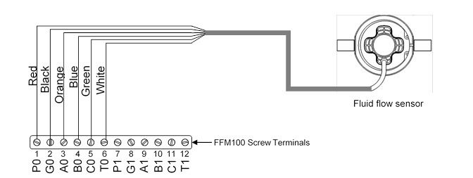
Figure 2 – Fuel Flow Sensor Connection Diagram
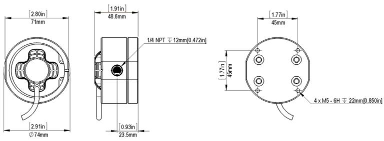
Figure 3 - Fuel Flow Sensor Mechanical Drawing
Fuel Flow Sensor Specifications
|
Part Number |
Flow Range |
Nominal K Factor |
|
M1AR |
2 LPH to 100 LPH (0.53 GPH to 26.4 GPH) |
1000 pulses/L (3785.4 pulses/Gal) |
|
M2AR |
25 to 500 LPH (6.6 to 132 GPH) |
400 pulses/L (1514.2 pulses/Gal) |
|
Specification |
Value |
|
Operating Temperature |
-40°C to 80°C (-40°F to 176°F) |
|
Storage Temperature |
-65°C to 170°C (-85°F to 338°F) |
|
Construction |
Housing Material: Aluminum O-Ring: FKM (Viton™) |
|
Port Size |
1/4” NPT Female |
|
Accuracy % Reading |
±0.25% (With K factor on sensor entered into FFM100) |
|
Maximum Viscosity |
1000 cPs |
|
Maximum Operating Pressure |
68.95 Bar (1000 PSI) |
|
Strainer Size |
200 Mesh (If not already installed after fuel filter) |
|
Cable Length |
1m (3.28 ft) |
|
Weight |
M1AR: 775g (1.71 lb), M2AR: 755g (1.66 lb). |
|
Dimensions |
74 x 71 x 48.6 mm (2.91 x 2.80 x 1.91 in.) |
For installation support, please contact:
Maretron, LLP
9014 N. 23rd Ave #10
Phoenix, AZ 85021
Telephone: (+1) 866-550-9100
E-mail: [email protected]