
Garmin MFD / MPower Setup Guide

Revision 1.3
Copyright © 2022 Carling Technologies, Inc.
60 Johnson Ave.
Plainville, CT 06062 USA
All Rights Reserved
Revision History
|
Revision |
Description |
|
1.0 |
Initial Release 3/8/2021 |
|
1.1 |
Updates for Garmin software release v23.5 or higher |
|
1.2 |
Screenshot update |
|
1.3 |
Updates for Garmin software release v26.1 or higher |
Table of Contents
Enable Garmin Switching Page / Adding a Page
Understanding Garmin Switch Numbers
Adding a Switching Page Overlay
Saving a Switching Page Preset
Warning: Carling Technologies is not responsible for property damage of any kind, personal injury, or death as a result of operating any manufacturer's multifunction display equipment, as well as any Carling or Maretron equipment. The vessel operator and its navigational aids assume all risks pertaining to any vessel where MPower®, Maretron®, or Carling Technologies equipment must be used to operate a vehicle of any kind.
Requirements
NMEA 2000
To control MPower devices from Garmin® MFD ensure that all MPower devices needing to be controlled by Garmin are on the same NMEA 2000 network. If the devices needing to be controlled by Garmin are not on the same NMEA 2000 network then the usage of a Maretron NBE100 (Network Bus Extender) may be required to “Bridge” networks where applicable. For more information on NMEA 2000® networking please visit the NMEA organization’s website at:
Garmin MFD Model
Not all Garmin brand MFDs support Digital Switching control. Be sure that your Garmin MFD supports Digital Switching. The following list of Garmin MFD series support Digital Switching provided a software version of 24.00 or higher is installed.
· GPSMAP® 74xx/xsv series
· GPSMAP 76xx/xsv series
· GPSMAP 8xxx series
· GPSMAP 84xx series
· GPSMAP 86xx series
· GPSMAP 7x2 series
· GPSMAP 9x2 series
· GPSMAP 12x2 series
· GPSMAP 7x2 Plus series
· GPSMAP 9x2 Plus series
· GPSMAP 12x2 Plus series
· GPSMAP 7x3 series
· GPSMAP 9x3 series
· GPSMAP 12x3 series
· GPSMAP A12
· GPSMAP 10x2 series
· GPSMAP 12x2 series
· Volvo® Penta Glass Cockpit 8xxx series
· Volvo Penta 76xx/xsv series
· Volvo Penta 86xx series
· Volvo Penta A series
· Volvo Penta B series
· EchoMAP® UHD series (*menu structure differs slightly from this document)
· EchoMAP Ultra series (*menu structure differs slightly from this document)
Setup Concept
Garmin Brand MFD allows for an intuitive, personalized setup arrangement for MPower digital switching.
· Create “Pages” for categorized circuits such as “Lighting”, “Pumps”, and “Accessories” or “Port Deck”, “Foredeck”, “Aft deck”.
· Add the circuits you desire to each page and name the circuits as you wish.
· Change the name of a circuit anytime as your vessel requires.
· Add a photo of your vessel to any “switching page” and apply circuit icons overlayed across the photo that will show when an item is On / Off.
· Switch items On / Off on any Garmin “switching page” and save the current settings as a preset to how you desire your vessel circuits to be On or Off, then recall this preset anytime.
· A Garmin “switching page” can have critical data added to it such as engine vitals or Heading so that the “switching page” can become a vital vessel operation page while navigation is underway.
· Save the Garmin “System Profile” to copy to an upgraded Garmin device to keep your settings or for excellent OEM page setup repeatability.
·
Synchronization between Garmin devices for all switch
configuration settings and switching page settings over Garmin Marine Network
(Ethernet).
Setup Process / Features
Enable Garmin Switching
Page / Adding a Page
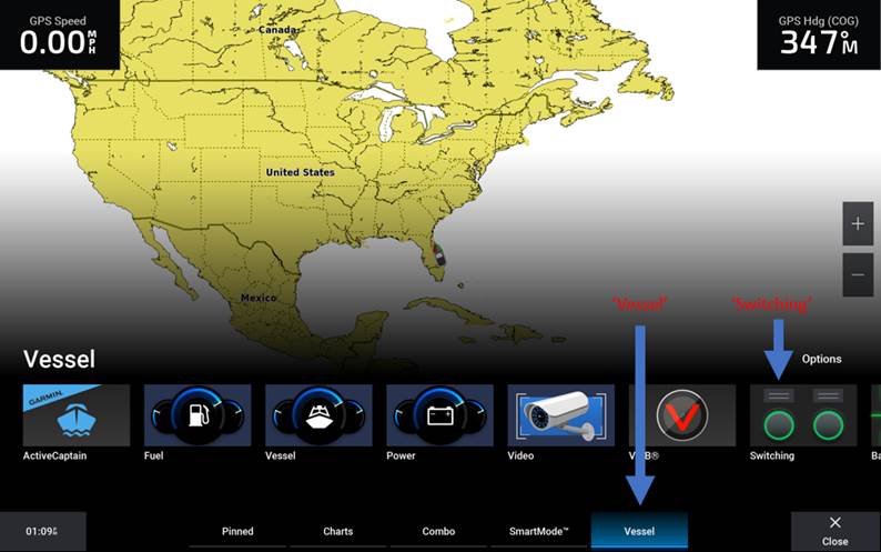
Any Garmin MFD compatible to control digital switching will have an icon appear that reads ‘Switching’ this icon will be found by pressing ‘Home’; ‘Vessel’; ‘Switching’.
· If the ‘Switching’ icon does not appear, please check the Garmin unit’s NMEA2000 connection.
First step in the process to customize your Garmin ‘Switching page(s)’ is to check if a ‘Switching Page’ appears. If the page is blank as shown below, it will be necessary to enable the ‘Switching Page’ by ‘Adding a Page’.
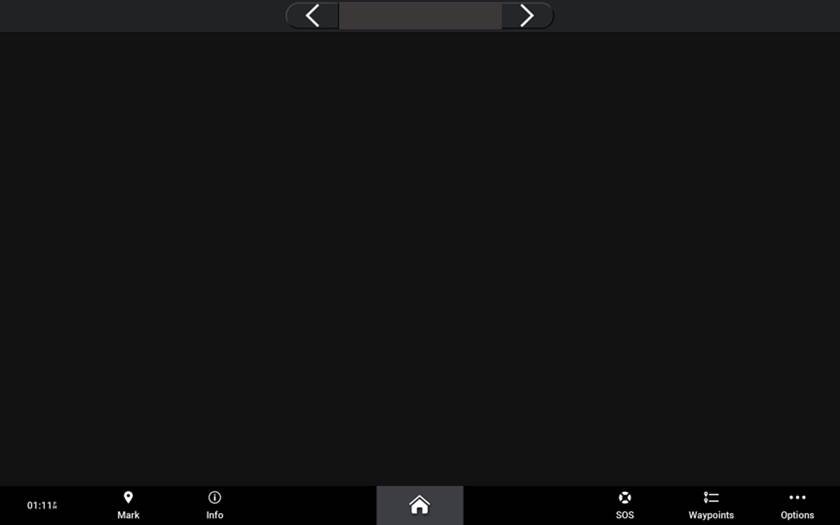
To add a page follow this process:
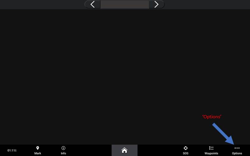
1) From the ‘Switching Page’ Press: ‘Options’
2) Press: ‘Setup’
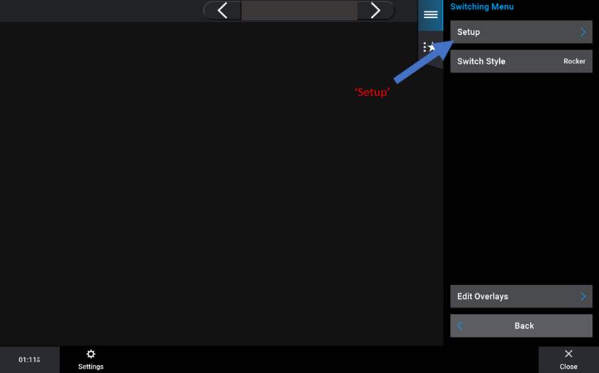
3) Press: “Add Page”
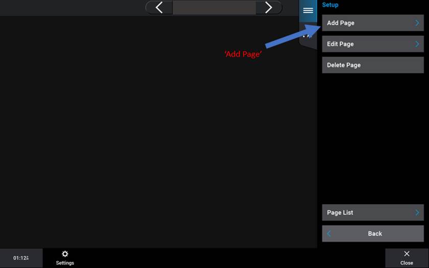
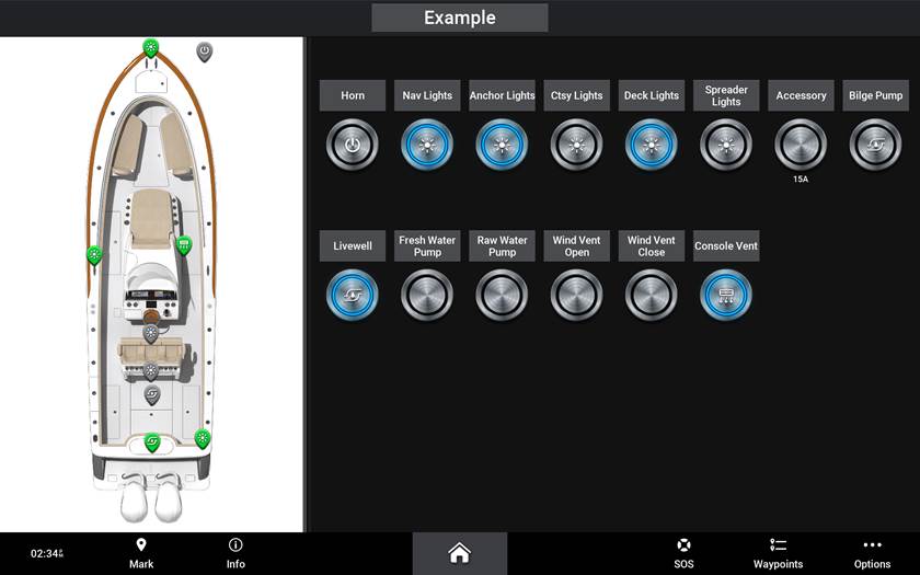
4) See ‘Default View’ of ‘Switching Page’ appear (Example Below)
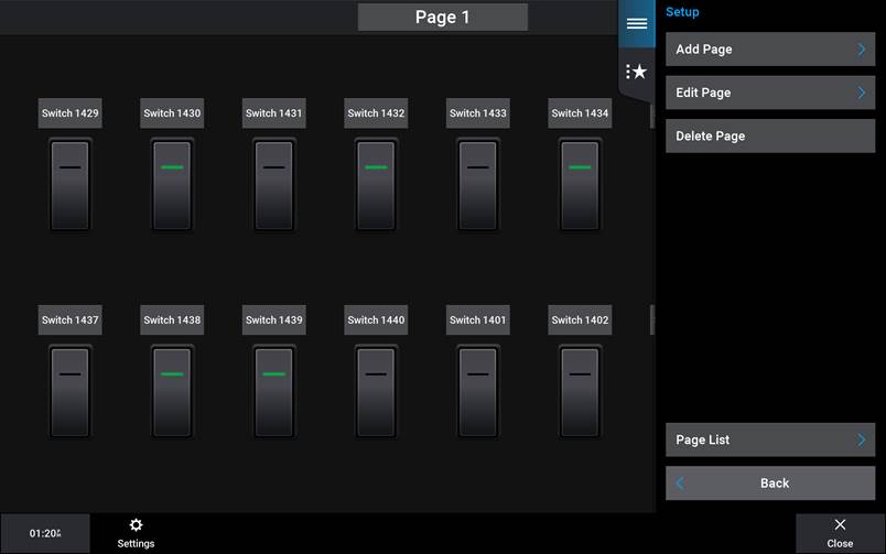
· If your ‘Switching Page’ reads ‘Not Available’ after ‘Adding a Page’ please check the Garmin unit’s NMEA2000 connection.
Understanding Garmin Switch Numbers
Understanding Garmin switch numbers are vitally important to configuring the ‘Switching
Page(s)’. Once these numbers origination are understood, formulating user friendly
‘Switching Page(s)’ could take only minutes.
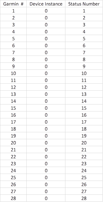
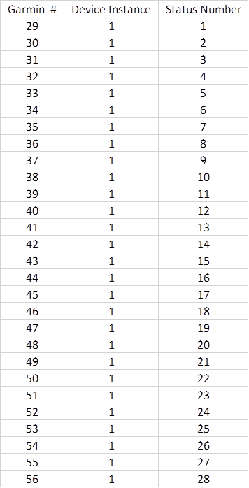
The Garmin numbers formulated for NMEA Standard digital switching systems are
based on NMEA 2000 PGN 127501 instance and status number (Indicator number). Each
NMEA 2000 127501 PGN Instance has 28 status number fields. These status numbers
start the Garmin switch number count starting at Instance number 0. For
example, Garmin switch number ‘1’ belongs to Digital
Switching device ‘Instance 0’ and controls ‘Channel 1’, Garmin switch
number ‘28’ belongs to Digital Switching device ‘Instance 0’ and controls ‘Channel
28’, Garmin switch number ‘29’ belongs to Digital Switching device ‘Instance 1’
and controls ‘Channel 1’ and Garmin switch number ‘56’ will belong to Digital
Switching device ‘Instance 1’ and controls ‘Channel 28’. With understanding of
this sequence, Garmin switch number ‘953’ will belong to Digital Switching
device ‘Instance 34’ and controls ‘Channel 1’. Note some NMEA 2000 devices use
more than one Instance Number to expand the number of channels used by that
device. See sequence visual example below for further understanding.
Naming / Configuring Switches
For maximum efficiency when
setting-up an MPower system with Garmin, each switch will have to be named and
configured ahead of building the ‘Switching Page’. It is advantageous to know
what circuit names and behavior is desired before configuring the switches. You
can name, label, and configure the switches in one location prior to
configuring your ‘Switching Page(s)’ Please follow the outlined process below for
the most efficient way to setup your ‘Switching Page(s)’
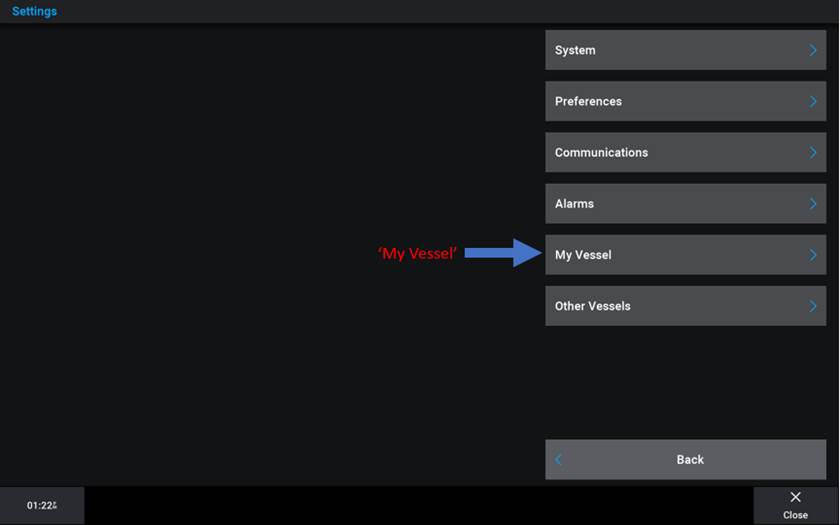
1) From any
screen, press: ‘Options’ then ‘Settings’.
When the following page appears, press ‘My Vessel’.
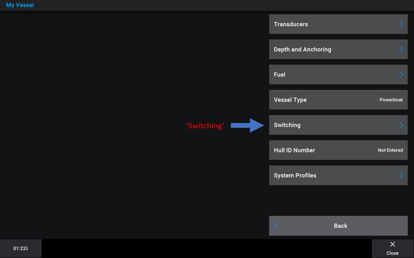
2) Press ‘Switching’
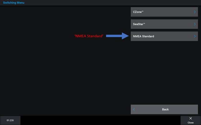
3) Press ‘NMEA Standard’
4) The following screen is where the switches will need to be configured for their name, label, desired behavior and whether the switch will be visible or hidden.
· You can also name switches inside the ‘Switching Page’ however that method is best suited for minor changes.
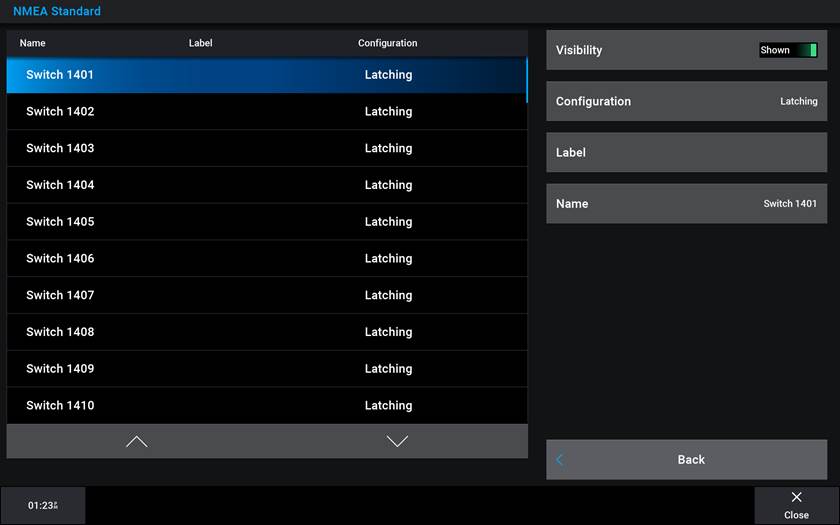
Visibility:
When selected to ‘Shown’ the switch will be visible and able to be used inside
the
‘All Switches List’ later used when setting-up the ‘Switching page(s)’. When
selected to ‘Hidden’ the switch will not appear as an option to choose inside
the ‘All Switches List’ when later building the ‘Switching Page(s)’. Reference
the Garmin switch number definition to understand which switch numbers you wish
to ‘Hide’ and wish to set visibility to ‘Shown’.
Configuration:
Garmin supports two switch behaviors; these switch behavior type names are ‘Momentary’
and ‘Latching’. Latching switch type operates where one press turns the load on
and the next turns the load off. Momentary switch type operates where the load
is turned on only when the switch is being actively pressed and turns off
immediately after the switch is no longer being pressed.
Label:
The ‘Label’ field supports 5 spaces to label your switches short name such
as ‘Fwd’, ‘Aft’, ‘Port’, ‘Stbd’, ‘Front’, ‘Rear’, or in the case of if the
circuit was a future-use ‘Accessory’ switch then maybe this field could state the
max current capacity of the circuit such as ‘15A’, ‘10A’, ‘5A’, Etc. to
represent how many amps current the circuit has been configured for.
Name:
Enter the switch’s desired primary name by entering the ‘Name’ menu.
Once all the ‘NMEA Standard’ switch configuration is complete you are ready to navigate back to the ‘Switching Page’ to begin customization.
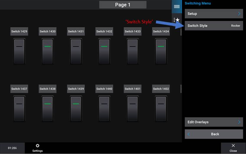
Switch Styles
Garmin supports three switch visual styles, these switch Styles are ‘Rocker’, ‘Silver Push Button’ and ‘Black Push Button’ these switch styles have no effect on the switch behavior and is only an appearance difference.
To change switch styles, follow this process:
1) From any menu press: ‘Home’; ‘Vessel’ then ‘Switching’ to get to the ‘Switching Page’
2) Once on the ‘Switching Page’ press ‘Options’ located in the lower right corner of the screen.
3) In the ‘Switching Menu’ press ‘Switch Style’
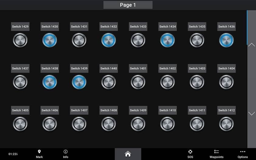
Switch Style, ‘Silver Push Button’:
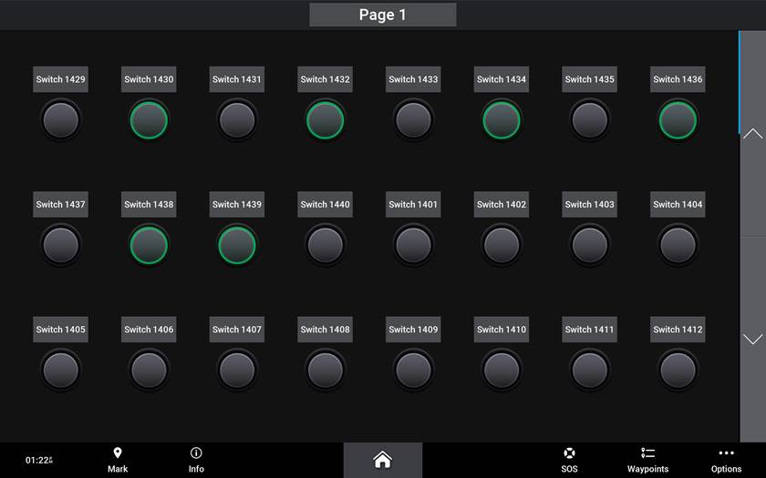
Switch Style, ‘Black Push Button’:
Changing a Page Name
To change a page name, follow this process:
1) From the ‘Switching Page’ press ‘Options’
2) Press: ‘Set Up’
3) Press: ‘Edit Page’
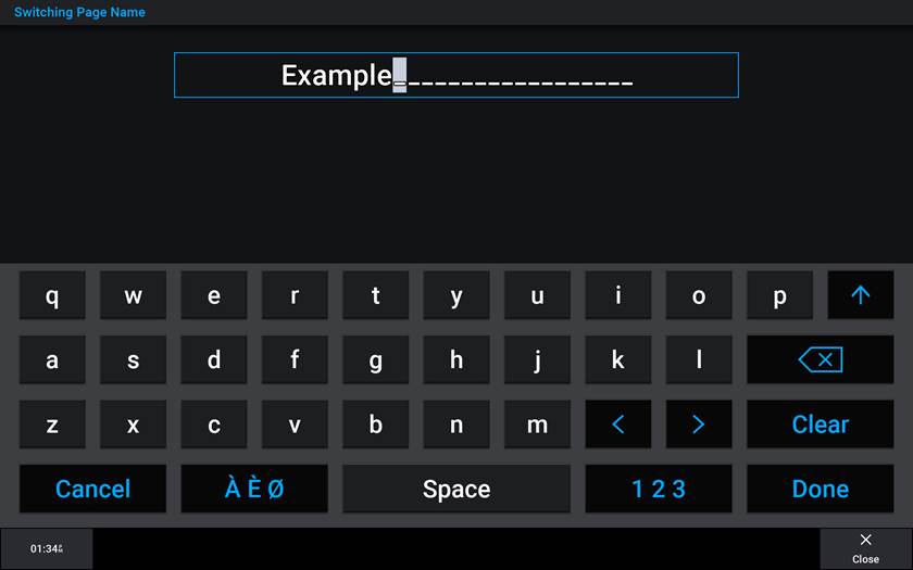
4) Press: ‘Name’
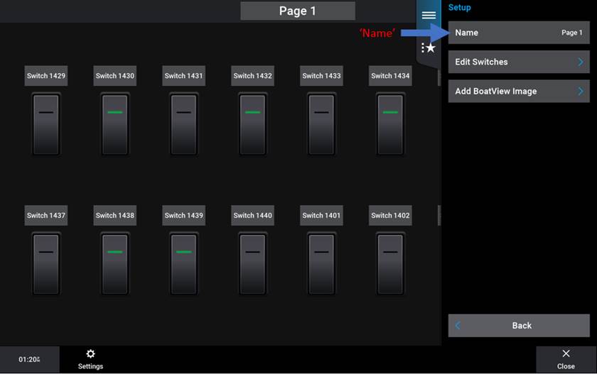
5) Type desired name into buffer
Deleting Switches
The default view of the Garmin ‘Switching Page’ shows all available switches. The Garmin ‘Switching page’ has a limited buffer size per page. This buffer limit changes based on which MFD is being used, which switch style is being used, and what else is on the screen alongside the switching page. For customization of the ‘Switching page’ with limited effort it is best to start with a blank page. Deleting all visible switches on the page can be more efficient than re-arranging the switches. It is recommended to delete all visible switches before starting to build the ‘Switching Page(s)’.
To Delete Switches, follow this process:
1) From the “Switching Page” press: “Menu”
2) Press: “Set Up”
3) Press: “Edit Page”
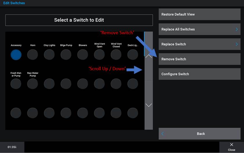
4) Press: “Edit Switches”
5) Highlight desired switch and Press: “Remove Switch”
· Ensure you scroll up / down the page to delete all switches
Adding / Replacing Switches
Adding Switches to the ‘Switching Page’ can be done in any open switch location. Once the switches are in their desired places you can also simply swap one switch for another for further fine adjustments. Both actions require almost the same process to achieve.
To Add or Replace Switches, follow this process:
1) From the ‘Switching Page’ press: ‘Options’
2) Press: ‘Set Up’
3) Press: ‘Edit Page’
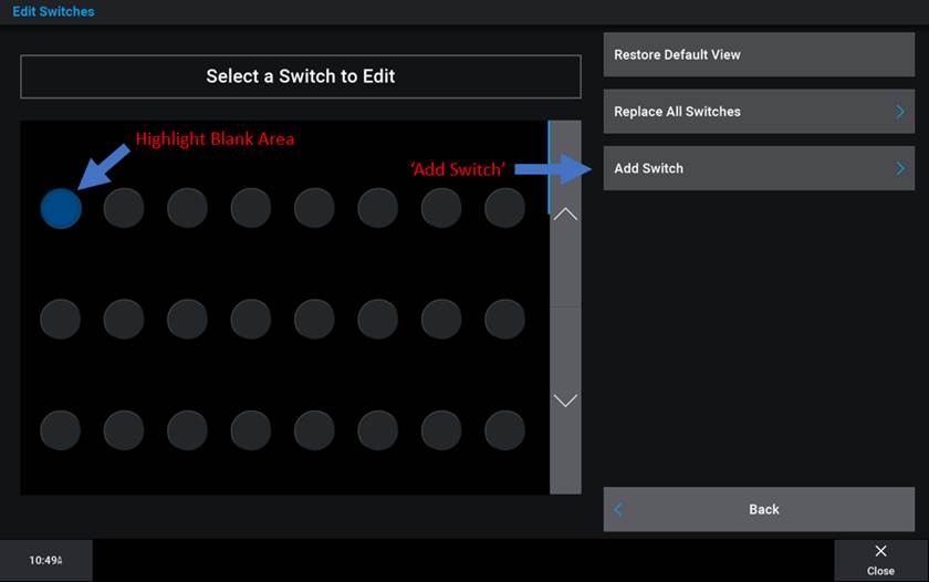
4) Press: ‘Edit Switches’
5) A) Highlight blank location to add desired switch and press ‘Add Switch’, select: ‘All’ switch category, find and select desired switch
· ‘All Switches’ category contains only the switches configured in the ‘NMEA Standard’ as ‘Visible’
5) B) Highlight switch desired
to be replaced and press ‘Replace Switch’ select:
‘All’ switch category, find and select the desired switch
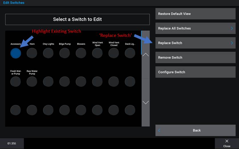
· ‘Replace Switch’ shortcut:
From ‘Switching Page’,(No Options Menu) press and hold on
a switch name.
Select new switch desired from list that appears.
Adding a “Boat View Image"
Adding a ‘Boat View Image’ is a great way to augment the ‘Switching Page’. Drop ‘Icons’ and ‘Place Switches’ on the ‘Boat View Image’ that are associated with the digital switching circuits for further customization. Garmin supports both .png and .jpeg file formats for the ‘Boat View Image’.
· It may be necessary to adjust the size of your ‘Boat View Image’ depending on the image size and MFD. Utilizing any software that can resize an image such as Microsoft® Paint® can accomplish the desired appeal for your image.
·
To Add a ‘Boat View Image’, follow this process:
1) Take photographs or use renderings of your vessel you desire to add to this page. Load these images to an SD or Micro SD card (depending on the MFD model) placed inside a folder named ‘Garmin’. If a ‘Garmin’ folder does not exist on your SD card, create one.
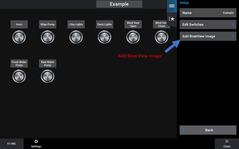
2) From the ‘Switching Page’ Press: ‘Options’
3) Press: ‘Set Up’
4) Press: ‘Edit Page’
5) Press: ‘Add Boat View Image’
6) Press: ‘Load from Card’
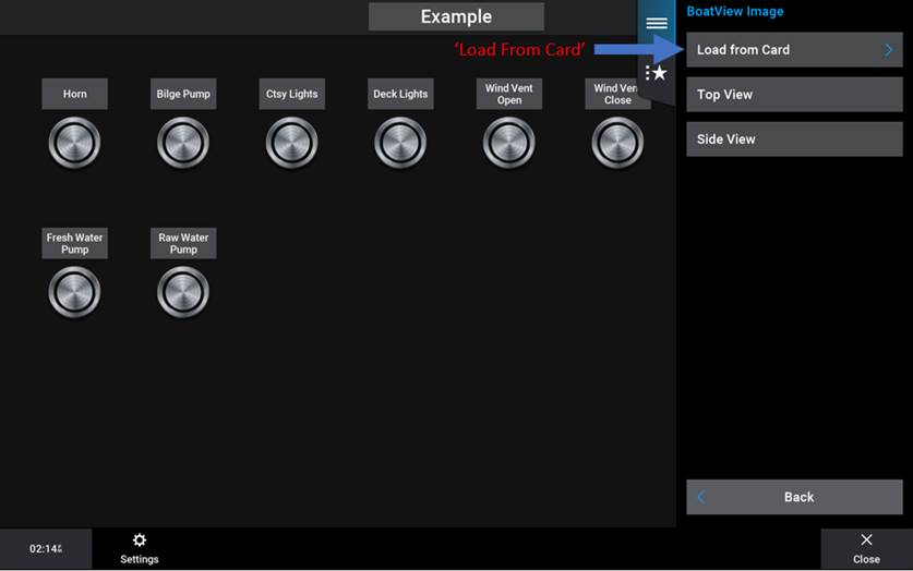
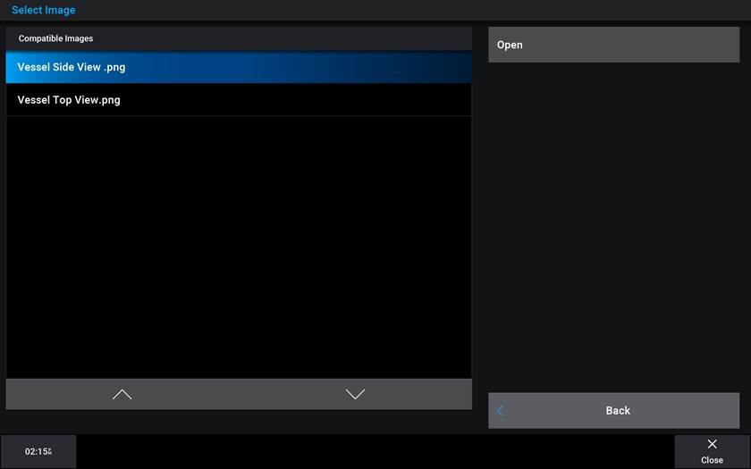
7) Select / Compare images you loaded onto card
Example ‘Horizontal’ orientation:
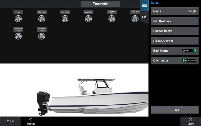
Example ‘Vertical’ orientation:
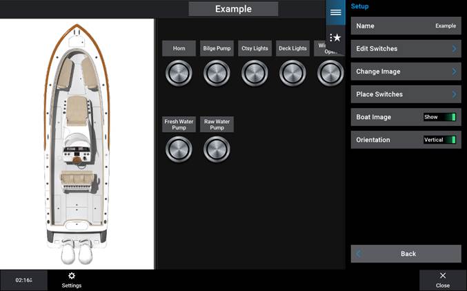
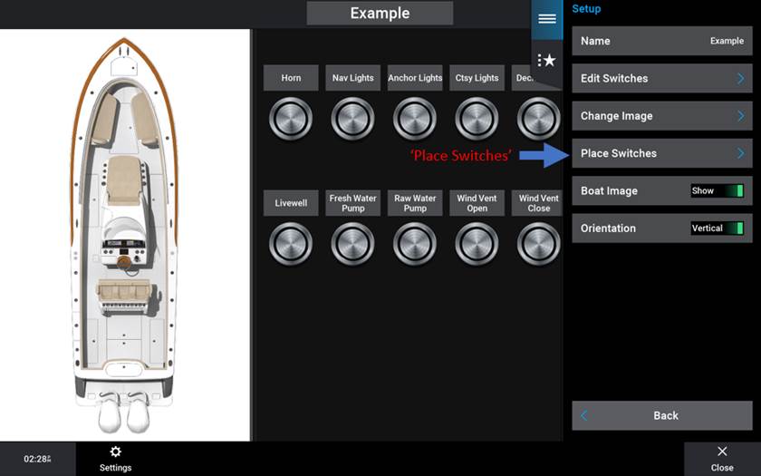
8) See your selected image. Next, to overlay / drop ‘Icons’ onto the image press: ‘Place Switches’
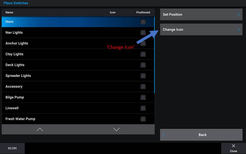
9) Select / highlight the switch you desire to ‘Place’ then Press: ‘Change Icon’
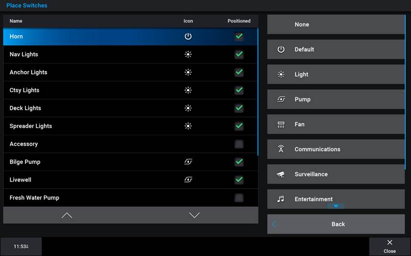
10) Select desired Icon from visual list of icon types
11) After selecting the desired icon for a switch, press: ‘Back’ then press ‘Set Position’, a crosshair icon will appear over your loaded image, move this crosshair icon using your finger on the touchscreen or using the four arrow keys at the bottom of the page. Once the desired position is reached, drop the circuit ‘Icon’ on the ‘Boat View Image’ by pressing ‘Set Position’.
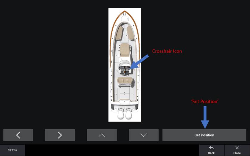
12) Repeat process as desired
Adding a Switching Page Overlay
Adding an ‘Overlay’ will allow you to fill pertinent data to the ‘Switching Page(s)’. You can use this feature to add almost any MFD data feature to the ‘Switching Page(s)’
· Please note that if you have multiple ‘Switching Pages’, ‘Overlay’ additions will be applied to all ‘Switching Pages’
To Add an ‘Overlay’, follow this process:
1) From the ‘Switching Page’ Press: ‘Options’
2) Press: ‘Edit Overlays’
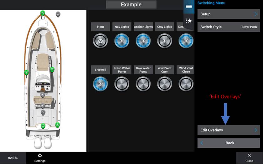
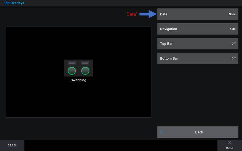
3) Select from ‘Data’, ‘Navigation’, ‘Top Bar’, or ‘Bottom Bar’. Choose ‘Top Bar’ or ‘Bottom Bar’ to show a ‘Compass Tape’, Choose ‘Navigation’ to show or hide Navigation data. A walkthrough procedure for the ‘Data’ addition will be shown step by step below. First, Press: ‘Data’
4) Select where you want ‘Data’ to appear. In this example ‘Side Bar’ was chosen.
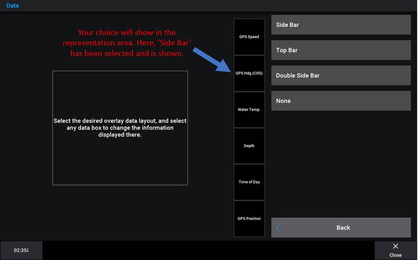
5) After choosing the location of ‘Data’ fill the desired data by selecting / highlighting each box containing data and then following the prompts to select the desired data to fill each box.
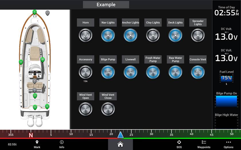
6) Press “Back” button until you see your new “Switching Page”
· The below example features ‘Data / Side Bar’ and ‘Bottom Bar / Compass Tape’
Saving a Switching Page Preset
A ‘Switching
Page Preset’ is a saved setting of some or multiple switch states. For example,
a ‘Preset’ could be named ‘Fishing Mode’ where the desire is that multiple
pumps needed for this mode will need to turn On. Saving a ‘Preset’ for ‘Fishing
Mode’ will allow for all desired pumps to turn On with the touch of a single
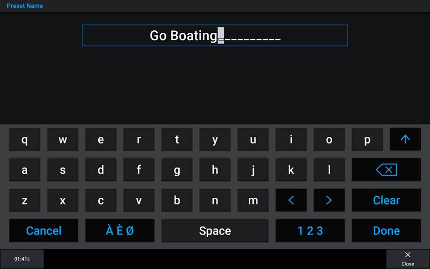
button. In the following Example a ‘Preset’ named ‘Go Boating’ will be added.
To add a ‘Preset’, follow this process:
1) From the ‘Switching Page’ Press: ‘Options’
2) Press the ‘Preset’ tab with the star
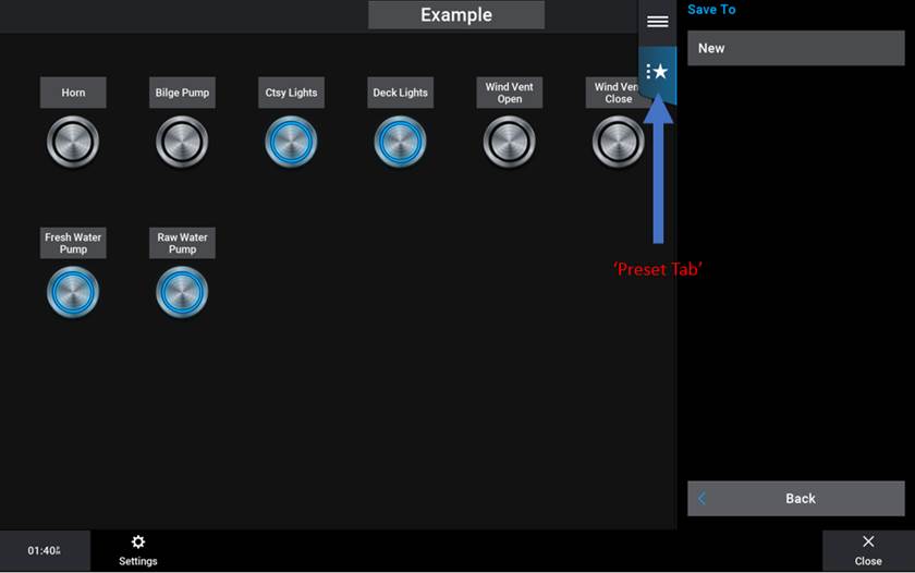
3) Press ‘New’
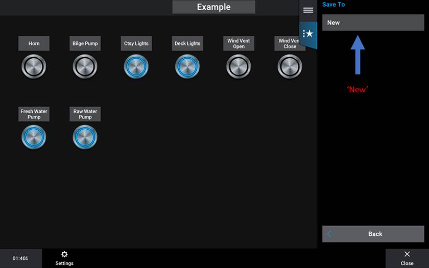
5) Highlight desired switches to be controlled and press: ‘Include’
Do this for each switch that is desired to be controlled. The current status of the ‘Included’ switch(s) will be what is saved for the ‘Preset’. There is also an option to ‘Include All’ or ‘Exclude All’. If a Green bar is present under the circuit ‘Value’, the circuit is On, if the green bar is extinguished the circuit is Off.
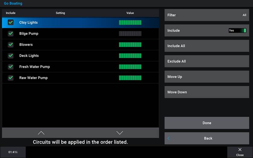
6) Once the ‘Include’ selection is complete press: ‘Done’
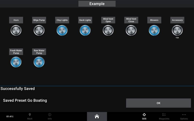
7) To use ‘Presets’ press: ‘Options’ then select the ‘Preset’
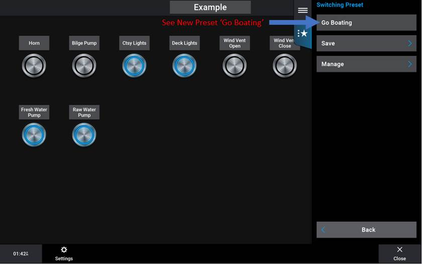
· See above: ‘Go Boating’ has been executed after pressing
Saving your ‘System Profile’
Saving your ‘System Profile’ enables all ‘User setup’ parameters to be saved to an SD card. This becomes very valuable to both the end user and the OEM for various reasons. In the case of the end user needing this data to be saved, the end user may desire to upgrade their MFD and when they do, having the ‘System Profile’ handy will eliminate the need for the customer to have to set-up the new MFD. In the case of the OEM, suppose an OEM has an assembly line of the same boat, one after another. It would be cumbersome to build each MFD profile including the ‘Switching Pages’ from default for each. Having this profile will allow the OEM to load their profile over and over again ensuring that nothing was missed and there is time efficiency on the assembly line.
To Save your ‘System Profile’, follow this process:
1) With an SD card inserted into the MFD’s SD card slot and from any page press: ‘Options’ in the bottom right corner of the screen then, ‘Settings’, ‘My Vessel’
2) Press: ‘System Profiles’
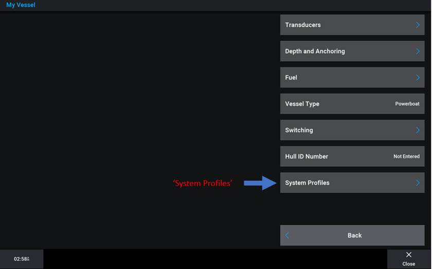
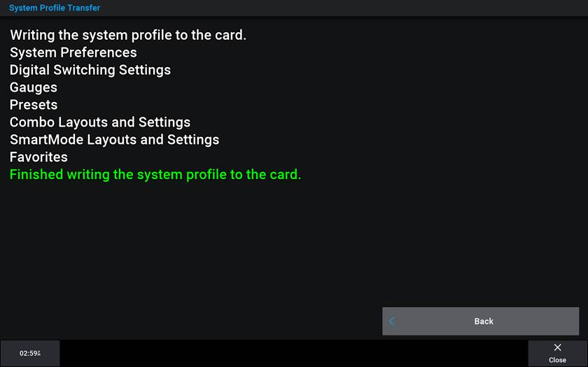
3) Press: ‘Save to Card’ then ‘New’. When prompted, enter the desired profile name and press: ‘Done’
· If ‘Save to Card’ does not appear, check your SD card is inserted into the Garmin. The SD card must use a FAT32 file system and cannot be an SDXC type. FAT32 is typically found in SD cards 32GB or less.
The same process is used to ‘Load a Profile’ to a Garmin, only when a ‘Profile’ is saved to an SD card and the SD card is inserted, press: ‘Import from Card’ in step 3 rather than ‘Save to Card’.
For More Information
For further information about Maretron’s MPower Digital Switching solutions, please visit,