1 General
1.1 Introduction
Congratulations on your purchase of the Maretron DSM200 NMEA 2000® Multi-function Graphic Display. Maretron has designed and built your display to the highest standards for years of dependable and accurate service.
Maretron’s DSM200 is a high-resolution monochrome display that allows easy interpretation of NMEA 2000® instrument and navigation data through custom display configurations, with an easy-to-use five-key illuminated keypad.
The Maretron DSM200 is designed to operate within the harsh demands of the
marine environment. However, no piece of marine electronic equipment can
function properly unless installed, configured, and maintained in the correct
manner. Please read carefully and follow these instructions for installation,
configuration, and usage of the Maretron DSM200 in order to ensure optimal
performance.
1.2 Firmware Revision
This manual corresponds to DSM200 firmware revision 1.13.
1.3 DSM200 Features
The Maretron DSM200 has the following features.
- NMEA 2000® Interface
- Waterproof NMEA 2000® Connector
- Sealed Waterproof Enclosure
- Powered Directly from NMEA 2000® Port
- Surface, Flush, or Gimbal Mounting
- Adjustable Red Backlighting of Screen and Keys Preserves Night Vision
- Visual and Audible Alarms
- User Configurable Favorite Screens
1.4 Quick Install
Installing the Maretron DSM200 display involves the following four steps. Please refer to the individual sections for additional details.
1. Unpack the Box (Section 2.1)
2. Choose a Mounting Location (Section 2.2)
3. Mount the DSM200 (Section 2.3)
- Connect the DSM200 (Section 2.4)
2 Installation
2.1 Unpacking the Box
When unpacking the box containing the Maretron DSM200, you should find the following items:
1 – DSM200 NMEA 2000® Multi-function Graphic Display
4 – Mounting studs
4 – Mounting washers
4 – Mounting lock washers
4 – Mounting knurled nuts
1 – DSM200 User’s Manual
1 – Warranty Registration Card
If any of these items are missing or damaged, please contact Maretron.
2.2 Choosing a Mounting Location
The DSM200 is housed in a waterproof enclosure (IEC IP67 rating – protected against the effects of temporary immersion in water) and can be mounted in either an outdoor location or an indoor location.
2.3 Mounting the DSM200
The DSM200 has three mounting options, which includes surface mounting, flush mounting, or gimbal mounting. Maretron suggests a location at which the display can be viewed from a relatively straight angle, and at which the keys are easily pressed.
2.3.1 Surface Mounting the DSM200
The DSM200 can be directly mounted to any suitable surface as shown in Figure 1. The steps for this type of mounting are as follows:
1. Attach the Surface Mount Template (see Section 11) to the surface where the DSM200 is to be located.
a. Make sure the template is level by using one of the horizontal lines as a guide.
b. Scotch tape works well for securing the template.
c. The maximum thickness of the mounting material should not exceed 1¼” using the provided mounting studs, thicker surfaces can be accommodated but you will need to purchase longer studs.
2. Drill the four mounting holes all the way through the mounting surface at the locations indicated on the Surface Mount Template.
a. Use a 3/16” drill bit.
3. Drill or cut a single hole for the electrical connector.
a. Use a 2¼” hole saw.
b. You will probably want this hole to be large enough for your fingers so that you can connect or disconnect the cable without removing the DSM200.
4. Remove the template from the mounting surface.
5. Insert the 2” studs into the back of the DSM200.
a. Make sure the studs are fully inserted into the back of the DSM200 but don’t over tighten the studs.
6. Insert the studs protruding from the back of the DSM200 through the mounting holes and secure with the provided hardware.
a. Place the flat washer on the stud first followed by the lock washer followed by the knurled nut.
b. Hand tighten the knurled nut.

Figure 1 – Surface Mounting the DSM200
2.3.2 Flush Mounting the DSM200
The DSM200 can be flush mounted to any suitable surface as shown in Figure 2. The steps for this type of mounting are as follows:
1. Attach the Flush Mount Template (see Section 11) to the surface where the DSM200 is to be located.
a. Make sure the template is level by using one of the horizontal lines as a guide.
b. Scotch tape works well for securing the template.
c. The maximum thickness of the mounting material should not exceed 1¼” using the provided mounting studs, thicker surfaces can be accommodated but you will need to purchase longer studs.
2. Cut out an opening as indicated on the Flush Mount Template.
a. Sorry, we should have made the flange larger, but be very careful not to go outside the indicated cutout area. Be on the safe side and cut the hole a little small and rasp or file to fit.
3. Remove the template from the mounting surface.
4. Insert the 2” studs into the back of the DSM200.
a. Make sure the studs are fully inserted into the back of the DSM200 but don’t over tighten the studs.
5. Remove the back of the case from the DSM200.
a. Place your thumbs on top of the studs and your finger along the side of the case and squeeze the back cover off the DSM200.
6. Insert the back of the DSM200 through the front side of the cutout.
7. Place the back cover on the opposite side of the mounting surface with the mounting holes aligned with the mounting studs and secure with the supplied hardware.
a. Place the flat washer on the stud first followed by the lock washer followed by the knurled nut.
b. Hand tighten the knurled nut.

Figure 2 – Flush Mounting the DSM200
2.3.3 Gimbal Mounting the DSM200
The DSM200 can be gimbal mounted to any horizontal surface such a counter or ceiling as shown in Figure 3. The gimbal mounting bracket is an optional accessory that includes necessary hardware for fastening the DSM200 to the gimbal mount.

Figure 3 – Gimbal Mounting the DSM200
2.4 Connecting the DSM200
The Maretron DSM200 provides a connection to an NMEA 2000® interface through a connector that can be found on the back of the unit.
The NMEA 2000® connector is a five pin male connector (see Figure 4). You connect the DSM200 to an NMEA 2000® network using a Maretron NMEA 2000® cable (or compatible cable) by connecting the female end of the cable to the DSM200 (note the key on the male connector and keyway on the female connector). Be sure the cable is connected securely and that the collar on the cable connector is tightened firmly. Connect the other end of the cable (male) to the NMEA 2000® network in the same manner. The DSM200 is designed such that you can plug or unplug it from an NMEA 2000® network while the power to the network is connected or disconnected. Please follow recommended practices for installing NMEA 2000® network products.
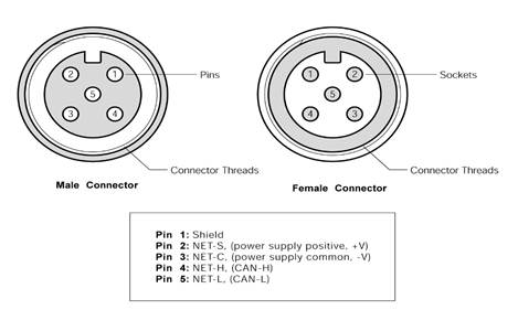
Figure 4 – NMEA 2000® Connector Face View
2.4.1 Checking the Connection
Once the NMEA 2000® connection to the Maretron DSM200 has been completed, check to see that information is being properly received by observing the display. One way to verify connectivity is to enter the data selection menu, which is described in Section 5.2.2.2. Refer to Section 8, “Troubleshooting”, if no information appears.
3 Operating the DSM200
3.1 Turning the DSM200 On
To turn on the DSM200, press the
power key (the leftmost of the five keys on the keypad). The DSM200 will
display a warning and ask you to press the Accept key (![]() ) to acknowledge
the warning and continue operation of the DSM200 (see Figure 5 below).
Alternatively, you may power down the DSM200 by pressing and holding the power
key (see Section 3.2 below for details).
) to acknowledge
the warning and continue operation of the DSM200 (see Figure 5 below).
Alternatively, you may power down the DSM200 by pressing and holding the power
key (see Section 3.2 below for details).

Figure 5 – DSM200 Powerup Screen
3.2 Turning the DSM200 Off
To turn the DSM200 off, press and hold the power key. The DSM200 will display a countdown screen, which can be seen in Figure 6. If you continue to hold the power key, the DSM200 will power down in approximately three seconds. If you release the power key before these three seconds have elapsed, the DSM200 will return to its current operational state.
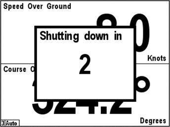
Figure 6 – Powerdown Countdown Screen
3.3 Keypad Essentials
The DSM200 has a five-key keypad located below the screen. Each key has slightly different functions depending on the operating mode. Figure 7 below shows the DSM200 keys and their names.

Figure 7 – Keypad and Key Names
In the normal viewing mode where your favorite screens are displayed, the keys on the DSM200 keypad have the following functions:
- Power
Key (![]() ) – turns the DSM200 off (see
Section 3.1 on page 7 for details).
) – turns the DSM200 off (see
Section 3.1 on page 7 for details).
- Lights
Key (![]() ) – cycles the backlight
brightness between off and the three programmed brightness levels (see Section 5.2.3.1 on page 76 for details).
) – cycles the backlight
brightness between off and the three programmed brightness levels (see Section 5.2.3.1 on page 76 for details).
- Up
Key (![]() ) – switches the display from
the current favorite screen to the next highest numbered favorite screen that
is enabled for that particular mode.
) – switches the display from
the current favorite screen to the next highest numbered favorite screen that
is enabled for that particular mode.
- Down
Key (![]() ) – switches the display from
the current favorites screen to the next lowest numbered favorite screen that
is enabled for that particular mode
) – switches the display from
the current favorites screen to the next lowest numbered favorite screen that
is enabled for that particular mode
- Enter
Key (![]() ) – changes from favorite
screens mode to menu mode
) – changes from favorite
screens mode to menu mode
In menu mode, a legend appears along the bottom of the screen displaying the function of each of the keys. The functions differ slightly depending on whether a menu is being accessed, a selection is being made from a list of possible data values, or a numeric value is being increased or decreased.
When accessing a menu, the keys on the DSM200 keypad have the following functions:
- Power
Key (![]() ) – turns the DSM200 off (see
Section 3.1 on page 7 for details).
) – turns the DSM200 off (see
Section 3.1 on page 7 for details).
- Back
Key (![]() ) – returns to the next
higher-level menu. If already at the top-level menu, returns to favorite
screens mode.
) – returns to the next
higher-level menu. If already at the top-level menu, returns to favorite
screens mode.
- Scroll
Up Key (![]() ) – changes the currently
selected (or highlighted) menu item from the presently selected one to the one
immediately above it. If the top menu item is already selected, the selection
wraps to the bottom menu item.
) – changes the currently
selected (or highlighted) menu item from the presently selected one to the one
immediately above it. If the top menu item is already selected, the selection
wraps to the bottom menu item.
- Scroll
Down Key (![]() ) – changes the currently
selected (or highlighted) menu item from the presently selected one to the one
immediately below it. If the bottom menu item is already selected, the
selection wraps to the top menu item.
) – changes the currently
selected (or highlighted) menu item from the presently selected one to the one
immediately below it. If the bottom menu item is already selected, the
selection wraps to the top menu item.
- Enter
Key (![]() ) – if the currently selected
menu item has a submenu, opens that submenu. If the currently selected menu
item has an editable value (indicated by a colon (:) followed by the data
value, moves the selection to the editable value and changes the keys to edit
mode.
) – if the currently selected
menu item has a submenu, opens that submenu. If the currently selected menu
item has an editable value (indicated by a colon (:) followed by the data
value, moves the selection to the editable value and changes the keys to edit
mode.
When editing a value chosen from a list, the keys on the DSM200 keypad have the following functions:
- Power
Key (![]() ) – turns the DSM200 off (see
Section 3.1 on page 7 for details).
) – turns the DSM200 off (see
Section 3.1 on page 7 for details).
- Back
Key (![]() ) – aborts the edit and
restores the editable value to its previous value
) – aborts the edit and
restores the editable value to its previous value
- Scroll
Up Key (![]() ) – changes the currently
selected editable value from the presently selected one to the one immediately
above it in the list of possibilities. If the top menu item is already
selected, the selection wraps to the bottom menu item.
) – changes the currently
selected editable value from the presently selected one to the one immediately
above it in the list of possibilities. If the top menu item is already
selected, the selection wraps to the bottom menu item.
- Scroll
Down Key (![]() ) – changes the currently
selected editable value from the presently selected one to the one immediately
below it in the list of possibilities. If the bottom menu item is already
selected, the selection wraps to the top menu item.
) – changes the currently
selected editable value from the presently selected one to the one immediately
below it in the list of possibilities. If the bottom menu item is already
selected, the selection wraps to the top menu item.
- Enter
Key (![]() ) – Accepts the currently
displayed value and stores it.
) – Accepts the currently
displayed value and stores it.
When editing a numeric value, the keys on the DSM200 keypad have the following functions:
- Power
Key (![]() ) – turns the DSM200 off (see
Section 3.1 on page 7 for details).
) – turns the DSM200 off (see
Section 3.1 on page 7 for details).
- Cancel
Key (![]() ) – aborts the edit and
restores the editable value to its previous value
) – aborts the edit and
restores the editable value to its previous value
- Increase
Key (![]() ) – increases the editable
value
) – increases the editable
value
- Decrease
Key (![]() ) – decreases the editable
value
) – decreases the editable
value
- Accept
Key (![]() ) – Accepts the currently
displayed value and stores it,
) – Accepts the currently
displayed value and stores it,
4 Important Concepts
4.1 Favorite Screens
The DSM200 can display many different types of information in many different configurations. It is capable of displaying up to four distinct measurements on its screen at one time. Rather than making you select from among the many types of available information any time you want to change the displayed data, the DSM200 has the concept of “Favorite Screens”. A “Favorite Screen” is a combination of display settings, data to display, and formats in which to display the data. The DSM200 supports up to 8 different favorite screens.
4.2 Categories and Data Types
The DSM200 is capable of displaying many types of information. In order to make it easier to locate a specific type of information to display, the different types of information are organized into general categories:
1. AC Power
2. Battery
3. Depth
4. Engine
5. Environment
6. Fuel Management
7. GPS
8. Heading
9. Navigation
10. Rudder
11. Speed
12. Tank
13. Time
14. Transmission
15. Vessel
16. Wind
The following sections explore each category in detail and spell out all of the data types that are available for display, if the appropriate sensors are installed in the network.
4.2.1 AC Power
- Gen. AC Current – displays the electrical current being sourced from a generator
- Gen. AC Frequency – displays the frequency of the AC power from a generator
- Gen. AC Voltage – displays the RMS voltage of the AC power from a generator
4.2.2 Battery
The DSM200 supports the display of information for up to sixteen batteries.
- Current – displays the electrical current being sourced to/from the battery
- Voltage – displays the voltage measured at the battery
- Temp. – displays the battery case temperature
4.2.3 Depth
- Transducer Offset – displays the offset being used by a depth transducer
- Water – displays the current reading from a depth transducer
4.2.4 Engine
The DSM200 supports the display of information for up to four engines.
- Boost Pressure – displays the boost pressure of a supercharger or turbocharger
- Engine Hours – displays the number of hours of operation reported by the engine
- Fuel Pressure – displays the pressure of the fuel for the engine
- Fuel Rate – displays the rate of fuel consumption for the engine
- Oil Pressure – displays the engine’s oil pressure
- Oil Temp – displays the engine’s oil temperature
- Tachometer – displays the rotational speed of the engine
- Tilt/Trim – displays the tilt or trim of the drive
- Voltage – displays the electrical power supply voltage measured at the engine
- Water Pressure – displays the engine’s water pressure
- Water Temp – displays the engine’s water temperature
4.2.5 Environment
- Barometer – displays the current atmospheric (barometric) pressure
- Heat Index – displays the current heat index based on air temperature and humidity
- Humidity Inside – displays the relative humidity from an indoor humidity sensor
- Humidity Outside – displays the relative humidity for an outdoor humidity sensor
- Moon Phase – displays the phase of the moon at the current time and position
- Sunrise – displays the local time of sunrise for the current day and position
- Sunset – displays the local time of sunset for the current day and position
- Temp. Dew Point – displays the current dew point based on air temperature and humidity
- Temp. Engine Room – displays the air temperature from a sensor mounted in an engine room
- Temp. Inside – displays the air temperature from a sensor mounted inside the vessel
- Temp. Main Cabin – displays the air temperature from a sensor mounted inside the main cabin
- Temp. Outside – displays the air temperature from a sensor mounted outside
- Temp. Sea – displays the current temperature of the water
- Twilight AM – displays the time of nautical twilight before sunrise for the current day and position
- Twilight PM – displays the time of nautical twilight after sunset for the current day and position
- Weather – displays a screen with a wide variety of weather-related data (See Section 6.7 for details)
- Wind Chill – displays the current wind chill based on air temperature and wind speed
4.2.6 Fuel Management
- Total Fuel Economy – displays the distance traveled per unit fuel used (for example, miles per gallon or kilometers per liter) for all engines whose data has been enabled in the Configuration->Data Enable menu (see Section 5.2.2.1.1 for details)
- Total Fuel Rate – displays the rate of fuel usage per unit time (for example, gallons or liters per hour) for all engines whose data has been enabled in the Configuration->Data Enable menu
- Total Fuel Remaining – displays the total fuel remaining in all fuel tanks whose data has been enabled in the Configuration->Data Enable/Disable menu
4.2.7 GPS
- Course Over Ground – displays the current Course Over Ground (always referenced to true north)
- Lat/Lon – displays the current latitude and longitude of the vessel
- Speed Over Ground – displays the current speed over ground
- Status – displays the current operating mode and status of the currently selected GPS receiver (please see Section 6.3, “GPS Status Display”, on page 89 for more details)
4.2.8 Heading
- Magnetic/True (depending on Heading Units Setting) – displays the current heading of the vessel (the direction the vessel is pointing)
- Rate of Turn – displays the angular rate of rotation of the vessel about the vertical axis
- Variation – displays the magnetic variation used to convert between true and magnetic headings
4.2.9 Navigation
The DSM200 is not a primary navigation device; that is, it does not provide means for entering and storing waypoint and route data. The DSM200 can receive information on the current leg of the voyage from a primary navigation device (such as a chart plotter or PC with navigation software and NMEA 2000® interface) and display this information.
- Bearing Origin to Destination – displays the direction from the origin waypoint to the destination waypoint
- Bearing To Waypoint – displays the bearing to the destination waypoint
- Course Over Ground – displays the current Course Over Ground (always referenced to true north)
- Cross Track Error – displays the cross-track error (minimum distance from the boat to the programmed route)
- Distance To Waypoint – displays the distance to the destination waypoint
- Est. Time of Arrival – displays the Estimated Time of Arrival at the waypoint
- Lat/Lon – displays the current latitude and longitude of the vessel
- Rolling Road – displays navigation information for the current leg of the route (see Section 6.5, ”Rolling Road”, on page 91 for details)
- Set/Drift – displays the direction (set) and speed (drift) of the water current
- Speed Over Ground – displays current Speed over Ground (relative to the earth, not the water)
- Time To Go – displays the estimated Time To Go until arrival at the waypoint
- VMG to Waypoint – displays the Velocity Made Good; that is, the speed at which the distance to the waypoint is decreasing
- Waypoint Number – this displays the number of the destination waypoint
4.2.10 Rudder
- Rudder Angle – displays the angle of the vessel’s rudder as indicated by the rudder sensor
4.2.11 Speed
- Through Water – displays the speed of the boat relative to the water
- Over Ground - displays Speed over Ground (relative to the earth, not the water)
- Total Log – displays the total distance traveled by the vessel since the log indicator was installed
- Trip Log – displays the distance traveled by the vessel since the trip indication of the log indicator was last reset
4.2.12 Tank
The DSM200 supports the display of information for up to sixteen tanks.
- Capacity – displays the fluid capacity of the tank
- Level – displays the level of fluid in the tank as a percentage of its capacity
- Remaining – displays the amount of fluid in the tank
4.2.13 Time
- Date Local – displays the current date referenced to the local time offset
- Date UTC – displays the current date referenced to Universal Time Coordinated
- Moon Phase – displays the phase of the moon at the current time and position
- Sunrise – displays the local time of sunrise for the current day and position
- Sunset – displays the local time of sunset for the current day and position
- Time Local – displays the current time referenced to the local time offset (see Section 5.2.6.11 on page 87 for details on how to set the local time offset.
- Time UTC – displays the current time referenced to Universal Time Coordinated (also known as Greenwich Mean Time, or GMT)
- Twilight AM – displays the time of nautical twilight before sunrise for the current day and position
- Twilight PM – displays the time of nautical twilight after sunset for the current day and position
-
4.2.14 Transmission
The DSM200 supports the display of information for up to four transmissions,
- Gear – displays the current gear of the transmission (forward, neutral, or reverse)
- Oil Pressure – displays the pressure of the oil in the transmission
- Oil Temp. – displays the temperature of the oil in the transmission
4.2.15 Vessel
- Pitch – displays the pitch of the vessel (rotation about the horizontal axis perpendicular to the ship’s keel)
- Roll – displays the roll of the vessel (rotation about the horizontal axis parallel to the ship’s keel)
- Trim Tabs – displays the position of the vessel’s trim tabs
4.2.16 Wind
- Dir. Apparent – displays the angle of the wind relative to the vessel center line as it appears to an observer on the deck of a moving or stationary vessel (does not subtract out the speed of the vessel)
- Dir. Ground Ref. – displays the angle of the wind relative to true or magnetic north (depending on the unit setting of the heading parameter, see Section 5.2.6.1) measured relative to a stationary observer, calculated using heading, course over ground (COG), and speed over ground (SOG)
- Dir. True Ves. Ref – displays the angle of the wind relative to the vessel center line (vessel’s speed is subtracted from Apparent wind direction), calculated using speed through water (STW) or speed over ground (SOG) (depending on the unit setting of the “Wind True Ves. Ref.” Parameter, see Section 5.2.6.4)
- Speed Apparent – displays the speed of the wind as it appears to an observer on the deck of a moving or stationary vessel (does not subtract out the speed of the vessel)
- Speed Ground Ref. – displays the speed of the wind relative to a stationary observer, calculated using heading, course over ground (COG), and speed over ground (SOG)
- Speed True Ves. Ref – displays the speed of the wind as it would appear to an observer if the vessel was stopped in the water, calculated using speed through water (STW) or speed over ground (SOG) (depending on the unit setting of the “Wind True Ves. Ref.” Parameter, see Section 5.2.6.5)
5 Operating Modes
The DSM200 has two main operating modes including normal viewing of information in the favorite screens mode (Section 5.1) and the menu mode (Section 5.2).
5.1 Favorite screens modes
On power up, the DSM200 always enters the favorite screens mode. In the favorite screens modes, the DSM200 displays one of up to eight “favorite” screens. Each “favorite” screen can display one, two, three, or four information displays. Each information display can show any displayable data in any display type supported by that data. In favorite screens mode, the DSM200 can operate in one of two ways:
1) in Manual mode, in which a particular “favorite” screen remains on the display until you selects another one, or
2) in Auto mode, where the DSM200 automatically cycles between “favorite” screens, at time intervals which are individually programmable for each “favorite” screen.
An example screen of the DSM200 running in favorite screens mode can be seen in Figure 8 below.

Figure 8 – DSM200 Running in Favorite Screens Mode
The very bottom left hand corner of the screen shows two important parameters: 1) it indicates which favorite screen is being displayed (in this case Favorite #5), and 2) it indicates that the DSM200 is currently operating in the Manual mode. Auto would appear in place of Manual if the DSM200 was operating in Auto mode.
5.2 Menu Mode
The menu mode is entered while
viewing favorite screens by pressing the Enter key (![]() ). In menu
mode, the DSM200 may be configured by scrolling up and down the menu and
selecting one of the submenus found there. The DSM200 main menu can be seen in Figure 9 below.
). In menu
mode, the DSM200 may be configured by scrolling up and down the menu and
selecting one of the submenus found there. The DSM200 main menu can be seen in Figure 9 below.
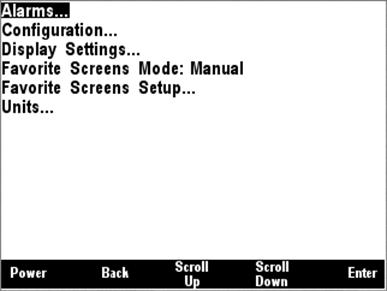
Figure 9 – Main Menu
5.2.1 Alarms Menu
Selecting Alarms from the main menu takes you to the Alarms menu shown below in Figure 10.
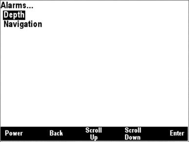
Figure 10 – Alarms Menu
The alarms menu allows you to configure the DSM200 to notify you if parameter values are outside of a range you specify. The following alarms are available in the DSM200:
Depth
Min Depth (minimum water depth)
Max Depth (maximum water depth)
Navigation
Max XTE (maximum cross-track error – this also sets the cross-track error limit used in the rolling road display – See Section 6.5, ”Rolling Road”, on page 91 for details)
You can enable or disable an alarm, select whether it is audible, program a reminder time for the alarm, and set the parameter value limits for the alarm as shown in Figure 11.
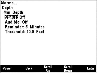
Figure 11 – Alarms Settings Menu
If the “Status” setting for the
alarm is “Off”, then that alarm is disabled. If the “Status” setting is “On”,
then the DSM200 display will monitor the value of the parameter and will
indicate an alarm condition if the parameter is less than (for “Min” alarms) or
greater than (for “Max” alarms) the value specified into the “Threshold”
field. You can adjust the “Status” setting by moving the highlight to the
“Status:” field by pressing the Scroll Up (![]() ) or Scroll
Down (
) or Scroll
Down (![]() ) keys, and then pressing the
Enter Key (
) keys, and then pressing the
Enter Key (![]() ). Once you have done this,
the highlight moves from the “Status:” title to the “On” or “Off” indication.
Press the Increase (
). Once you have done this,
the highlight moves from the “Status:” title to the “On” or “Off” indication.
Press the Increase (![]() ) or Decrease (
) or Decrease (![]() ) keys to cause the indication to change to the desired value, and
then press the Accept key (
) keys to cause the indication to change to the desired value, and
then press the Accept key (![]() ) to cause the current value
to be stored.
) to cause the current value
to be stored.
If the “Audible” setting for an
alarm is “On” and the “Status” is also set to “On”, then the DSM200 will beep
continuously from the time the alarm condition is triggered until the user
acknowledges the alarm. You may adjust this setting by scrolling to the
“Audible:” title, pressing the Enter key (![]() ), pressing
the Increase (
), pressing
the Increase (![]() ) and Decrease (
) and Decrease (![]() ) keys to adjust the setting to the desired value, and then pressing
the Accept key (
) keys to adjust the setting to the desired value, and then pressing
the Accept key (![]() ) to cause the current value
to be stored.
) to cause the current value
to be stored.
Once you acknowledge an alarm by
pressing the “Dismiss” key, the DSM200 will stop checking the alarm condition
for the time specified by the “Reminder” setting to allow you time to address
and correct the alarm condition. If the “Reminder” field is set to “0
Minutes”, then the DSM200 will always check the alarm, which means that the
alarm might be re-triggered immediately after it is acknowledged by the user.
The range of values for the “Reminder” setting is between 0 minutes and 60
minutes. You may adjust this setting by scrolling to the “Reminder:” title,
pressing the Enter key (![]() ), pressing the Increase (
), pressing the Increase (![]() ) and Decrease (
) and Decrease (![]() ) keys to adjust the setting
to the desired value, and then pressing the Accept key to cause the current
value to be stored.
) keys to adjust the setting
to the desired value, and then pressing the Accept key to cause the current
value to be stored.
The “Threshold” field determines
the alarm value that is used as the point at which the alarm is triggered. For
“Min” alarms, if the monitored parameter value is less than the value of the
“Threshold” setting, then the alarm will be triggered. For “Max” alarms, if the
monitored parameter value is greater than the value of the “Threshold” setting,
then the alarm will be triggered. The range of acceptable parameters for this
setting depends on the parameter being monitored. You may adjust this setting
by scrolling to the “Threshold:” title, pressing the Enter key (![]() ), pressing the Increase (
), pressing the Increase (![]() ) and Decrease (
) and Decrease (![]() ) keys to adjust the setting to the desired value, and then pressing
the Accept key (
) keys to adjust the setting to the desired value, and then pressing
the Accept key (![]() ) to cause the current value
to be stored.
) to cause the current value
to be stored.
5.2.2 Configuration Menu
The configuration menu allows you to change the types of data that are displayed, as well as which NMEA 2000® nodes are displayed. The configuration menu also allows you to configure certain types of Maretron NMEA 2000® devices. The available options within the Configuration screen are shown in Figure 12.
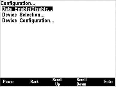
Figure 12 – Configuration Menu
5.2.2.1 Data Enable/Disable
The Data Enable/Disable allows you to configure whether or not certain categories of information appear in other menus. This allows you to configure the DSM200 so that information that is not available on the network does not clutter the operating menus. For example, in a vessel without a wind sensor, it is often desirable to disable display of the “Wind” data types when configuring favorite screens. Figure 13 shows the Data Enable/Disable menu.

Figure 13 – Data Enable/Disable Menu
5.2.2.1.1 Fuel Management Considerations
In order to use the fuel management features of the DSM200, it is important to understand how total fuel rate, total fuel economy and total fuel remaining are calculated.
The total fuel rate is calculated by adding together the fuel rates of all engines that have been enabled in the Data Enable/Disable menu. If any engine has been enabled in the Data Enable/Disable menu and it is not present or is not transmitting any data, then the DSM200 will not calculate the total fuel rate. If you notice that the DSM200 is not displaying a figure for the total fuel rate, check that all engines which have been enabled in the Data Enable/Disable menu are present and powered on.
The fuel economy is calculated by dividing the speed of the vessel, obtained from the GPS speed over ground, by the total fuel rate.
The total fuel remaining is calculated by adding the fuel remaining readings from all tanks of type “fuel” that have been enabled in the Data Enable/Disable menu. If any fuel tank that has been enabled in the Data Enable/Disable menu is not present or is not transmitting any data, then the DSM200 will not calculate the total fuel remaining. If you notice that the DSM200 is not displaying a figure for the total fuel remaining, check that all fuel tanks which have been enabled in the Data Enable/Disable menu are present and powered on.
5.2.2.2 Device Selection
The Device Selection menu allows you to select which NMEA 2000® devices are displayed on the DSM200. In this manner, multiple devices of the same type may be used in redundant and fail-safe configurations. The DSM200 Device Selection Menu for an example network configuration can be seen in Figure 14 below.
WARNING: Do not select multiple devices of the same type for display. This will result in multiple and possibly conflicting readings.
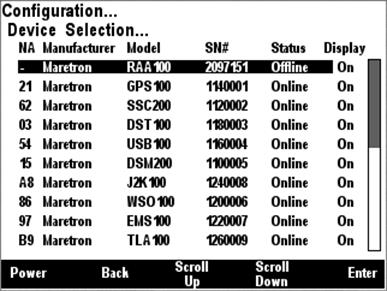
Figure 14 – Device Selection Menu
The “NA” column of the menu displays the node address the device is using.
The “Manufacturer” column of the menu displays the manufacturer of the device.
The “Model” column displays the model number of the device.
The “SN#” column displays the serial number of the device, so that any of two or more devices of the same manufacturer and model number may be distinguished from one another.
The “Status” column indicates whether the device is currently connected to the bus and is responding to queries (“Online”), or has been disconnected from the bus, has lost power, or for some other reason is not responding to queries (“Offline”).
The “Display” column
indicates whether data from that particular device is accepted for display by
the DSM200 (“On”) or that the DSM200 ignores data transmitted by this device
(“Off”). By scrolling to the device and pressing the Enter key (![]() ), you may then use the Scroll Up (
), you may then use the Scroll Up (![]() ) and Scroll
Down (
) and Scroll
Down (![]() ) keys to toggle the “Display”
status for this particular device. Once you are satisfied with the state of the
“Display” setting, press the Enter key (
) keys to toggle the “Display”
status for this particular device. Once you are satisfied with the state of the
“Display” setting, press the Enter key (![]() ) to accept
the setting.
) to accept
the setting.
The DSM200 will retain information on devices that have been removed from the bus or powered down (“Offline”) so that when they are placed back on the bus, they will assume their prior “Display” setting.
The DSM200 will automatically select (turn “On”) any new devices that it detects transmitting on the network. Therefore, if you add a new device to the network that transmits the same data as an existing network device, for example, a second GPS, then you must enter the Device Selection Menu and deselect one of the two devices.
5.2.2.3 Device Configuration
The Device Configuration menu enables you to configure certain types of devices on the NMEA 2000® network. Devices that may be configured using the DSM200 include the following:
1. Maretron SSC200 – set installation offset, perform magnetic deviation calibration, check magnetic deviation calibration status, invert installation, configure magnetic variation settings, setup NMEA0183 interface, program rate of turn damping, zero the rate-of-turn offset, and enable/disable individual NMEA 2000® PGN transmissions.
- Maretron DST100 – set transducer offset, zero trip distance log
- Maretron GPS100 – enable and disable WAAS functionality, set the GPS mode, program the elevation, PDOP and SNR masks, set the antenna altitude, force a cold start, enable/disable individual PGN transmission, and reset the unit back to its factory defaults.
- Maretron DSM200 – allows configuration of other DSM200s on network
5. Maretron USB100 – allows configuration of USB100s on network
6. Maretron WSO100 – set installation offset, set wind damping rates, and enable/disable individual NMEA 2000® PGN transmissions.
7. Maretron J2K100 – set J1939 node address, set NMEA 2000 engine/transmission instance, enable pass-through of J1939 diagnostic messages, and enable/disable individual NMEA 2000® PGN transmissions.
8. Maretron TLA100 – Set tank type and tank number, set operating mode, set tank capacity, and calibrate for irregular shaped tanks.
9. Maretron RAA100 – Set rudder number, operating mode, and calibrate rudder position.
10. Bennett EP-30 – Calibrate trim tabs.
More device types will be included in future firmware releases.
The Device Configuration menu is shown in Figure 15.

Figure 15 – Device Configuration Menu
The “HW” column shows the device hardware version.
The “SW” column shows the device software version.
5.2.2.3.1 Maretron SSC200 Configuration
Nine configurable parameters for the Maretron SSC200 solid state compass may be configured using the Maretron DSM200 display. The Maretron SSC200 configuration menu can be seen in Figure 16 below.

Figure 16 – Maretron SSC200 Configuration Menu
5.2.2.3.1.1 Magnetic Deviation Calibration
The DSM200 is capable of performing magnetic deviation calibration on a Maretron SSC200 solid state compass. The first screen (Figure 17) gives instructions for performing the procedure. First, begin to turn the boat in a slow circle (either clockwise or counter-clockwise) at about 3 to 12 degrees per second.
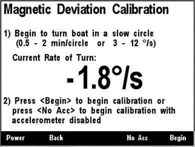
Figure 17 – Maretron SSC200 Magnetic Deviation Calibration Start Screen
Once you have begun the turn, press
Begin (![]() ) to start the calibration
procedure. If you do not wish to perform magnetic deviation calibration at this
time, press Abort (
) to start the calibration
procedure. If you do not wish to perform magnetic deviation calibration at this
time, press Abort (![]() ), and the currently stored
deviation tables will be retained.
), and the currently stored
deviation tables will be retained.
If you are in a large vessel, it
may be difficult to turn the vessel in a small enough circle to avoid
significant centrifugal force applied to the compass during magnetic deviation
calibration. This can cause the built-in tilt sensors inside the compass to
mistakenly believe that the compass is tilted during the magnetic deviation
calibration, which can adversely affect the quality of the magnetic deviation
calibration, especially in northerly latitudes where magnetic inclination
(magnetic dip) is higher. If this is the case, instead of pressing the Begin (![]() ) key, press the No Acc(
) key, press the No Acc(![]() ) key. This will cause the
compass to ignore its tilt sensors and assume that the compass is level to the
earth’s surface during the calibration. You must keep the boat level during
calibration if you choose this option.
) key. This will cause the
compass to ignore its tilt sensors and assume that the compass is level to the
earth’s surface during the calibration. You must keep the boat level during
calibration if you choose this option.
After you press the Begin (![]() ) key or the No Acc(
) key or the No Acc(![]() ) key, a status screen will
appear (Figure 18).
) key, a status screen will
appear (Figure 18).
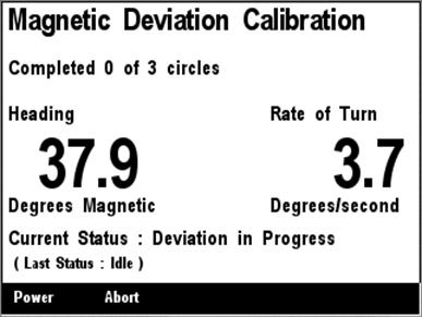
Figure 18 – Maretron SSC200 Magnetic Deviation Calibration Progress Screen
This progress screen shows the
number of circles completed, the current heading, the current rate of turn, and
the current status of compass calibration. If you do not wish to continue magnetic
deviation calibration at this time, press Abort (![]() ), and the
currently stored deviation tables will be retained. Once calibration is
successful, a completion screen will appear. If calibration is unsuccessful, a
screen will appear indicating this, and you should repeat the calibration
procedure.
), and the
currently stored deviation tables will be retained. Once calibration is
successful, a completion screen will appear. If calibration is unsuccessful, a
screen will appear indicating this, and you should repeat the calibration
procedure.
5.2.2.3.1.2 Magnetic Deviation Status
Pressing the Enter key (![]() ) with the
“Magnetic Variation Status” menu item selected causes the screen shown in Figure 19 to be displayed.
) with the
“Magnetic Variation Status” menu item selected causes the screen shown in Figure 19 to be displayed.

Figure 19 – Maretron SSC200 Magnetic Deviation Status Screen
5.2.2.3.1.3 Installation Offset Calibration
The installation offset (i.e., misalignment of installed
SSC200 with vessels center line) may be calibrated using the Maretron DSM200
display. Once the compass is installed, point the vessel at a known heading,
and then select the compass from the Device Configuration menu. Scroll down (![]() ) the menu items to the line entitled “Installation Offset Calibration”
and press enter (
) the menu items to the line entitled “Installation Offset Calibration”
and press enter (![]() ) which takes you to the screen
shown in Figure 20.
) which takes you to the screen
shown in Figure 20.
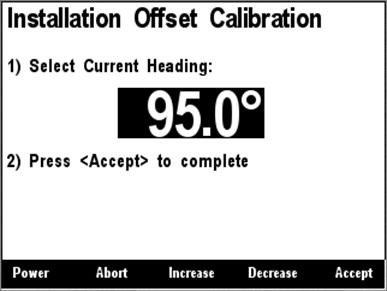
Figure 20 – Maretron SSC200 Installation Offset Calibration Screen
Use the Increase (![]() ) and
Decrease (
) and
Decrease (![]() ) keys to adjust the display value
until it matches the known heading to which the boat is pointed. Press the
Accept (
) keys to adjust the display value
until it matches the known heading to which the boat is pointed. Press the
Accept (![]() ) key to accept the value when you
are satisfied. If you do not wish to perform installation offset calibration
at this time, press the Abort (
) key to accept the value when you
are satisfied. If you do not wish to perform installation offset calibration
at this time, press the Abort (![]() ) key and the installation offset
will not be altered.
) key and the installation offset
will not be altered.
5.2.2.3.1.4 Inverted Installation Entry
Normally, the SSC200 is mounted so that the label on the compass is facing up and the NMEA 2000 and NMEA 0183 connectors are facing towards the bow of the vessel. Recent version of SSC200 firmware support mounting the compass upside-down (for instance, to a ceiling), or backwards (with connectors facing towards the stern of the vessel, so that the SSC200 can be mounted to the aft side of a bulkhead). If either of these mounting options is used, the DSM200 can be used to inform the SSC200 of this fact so that it can adjust heading, rate or turn, pitch, and roll readings to be corrected accordingly.

Figure 21 - Setting the Installation Orientation
The choices that are offered are “Normal Installation” (default), “Backward Installation”, “Upside-Down Installation”, or “Upside Down and Backward”.
5.2.2.3.1.5 Variation Source Entry
The SSC200, being a magnetic compass, transmits heading information referenced to the magnetic north pole (magnetic heading). The SSC200 is capable of transmitting heading information referenced to the earth’s geographic North Pole (true heading). In order to produce true heading, information regarding the magnetic variation at the current location is required. Please see the SSC200 User’s Manual for more details on the use of magnetic variation by the SSC200 compass.
By default, the SSC200 is capable of receiving variation information on either its NMEA 0183 or NMEA 2000® interfaces (please see Figure 22). This causes the SSC200 to use variation data from either the NMEA 0183 interface or the NMEA 2000® interface.

Figure 22 – Setting Variation Source to NMEA 0183 or NMEA 2000® (factory default)
You should need to alter this setting only if:
1) There are variation sources available on both the NMEA 2000® and NMEA 0183 interfaces, or
2) There is no magnetic variation source available.
If variation sources are available on both the NMEA 2000® and NMEA 0183 interfaces, you must tell the SSC200 which source to use. Figure 23 below shows the NMEA 0183 source selected. This causes the SSC200 to use variation data from the NMEA 0183 interface and ignore all other variation sources (i.e., NMEA 2000® interface and manual entries).

Figure 23 – Setting Variation Source to NMEA 0183 Only
Figure 24 below shows the NMEA 2000® source selected.
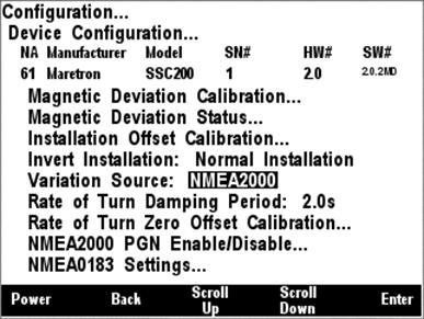
Figure 24 – Setting Variation Source to NMEA 2000® Only
If there is no magnetic variation
source available on either the NMEA 2000® or the NMEA 0183
interface, and you wish to display true heading information, you may manually
enter a magnetic variation. To set a manual variation value, you must change
the variation source by pushing the Enter key (![]() ) with the
“Variation Source” menu item selected. This highlights the next field where you
select “Manual Entry” by scrolling (
) with the
“Variation Source” menu item selected. This highlights the next field where you
select “Manual Entry” by scrolling (![]() or
or ![]() ) through the
options until you reach “Manual Entry”. Pressing the Enter key (
) through the
options until you reach “Manual Entry”. Pressing the Enter key (![]() ) with the “Manual Entry” menu item selected takes you to the screen
shown in Figure 25.
) with the “Manual Entry” menu item selected takes you to the screen
shown in Figure 25.
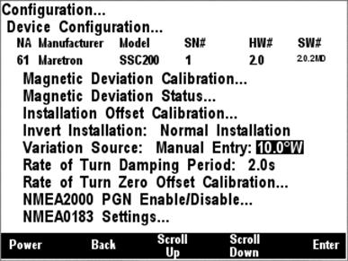
Figure 25 – Entering Manual Variation
Press the Scroll Up (![]() ) or Scroll Down (
) or Scroll Down (![]() ) key to change the amount of
East or West variation. Press the Accept Key (
) key to change the amount of
East or West variation. Press the Accept Key (![]() ) when the
desired number is shown. You may also disable manual variation by setting the
value to “Disable”; this option appears between the values 0.0°E and 0.1°W when
scrolling through the values. When manual variation is disabled, the SSC200
will not transmit any variation information and heading information will be
available only in magnetic heading format.
) when the
desired number is shown. You may also disable manual variation by setting the
value to “Disable”; this option appears between the values 0.0°E and 0.1°W when
scrolling through the values. When manual variation is disabled, the SSC200
will not transmit any variation information and heading information will be
available only in magnetic heading format.
WARNING: Magnetic variation changes as your location on the earth changes; therefore magnetic variation should be adjusted with changes in position. Neither the DSM200 nor the SSC200 will make these changes automatically; they are the responsibility of the user.
5.2.2.3.1.6 Rate of Turn Damping Period
The SSC200 is capable of transmitting the rate of turn of a vessel. Different applications may require different damping for the rate of turn measurement. The DSM200 may be used to set the damping period for the rate of turn measurement to anywhere between 0.1 seconds and 60 seconds. Figure 26 shows an example of the damping period set to 2 seconds.
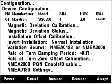
Figure 26 – Programming SSC200 Rate of Turn Damping Period
5.2.2.3.1.7 Rate of Turn Zero Offset Calibration
The DSM200 is capable of displaying rate of turn
information from a Maretron SSC200 compass. Although the compass provides very
accurate rate of turn information, it can drift off of zero even though the
vessel is not turning. Fortunately, the SSC200 can learn the zero offset for
different conditions found on the vessel. You teach the compass these zero offset
values by pressing the Enter key (![]() ) with the “Rate of Turn Zero
Offset Calibration” menu item selected which causes the DSM200 to display the
screen shown in Figure 27.
) with the “Rate of Turn Zero
Offset Calibration” menu item selected which causes the DSM200 to display the
screen shown in Figure 27.
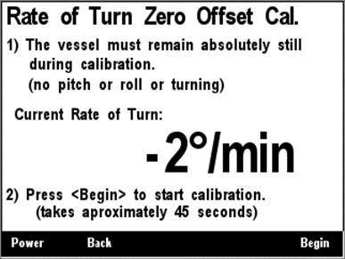
Figure 27 – Maretron SSC200 Rate of Turn Zero Offset Calibration Screen
5.2.2.3.1.8 NMEA 2000® PGN Enable/Disable
The SSC200 compass transmits several different messages,
which can be turned on or turned off by the DSM200 display. Pressing the Enter
key (![]() ) with NMEA2000®
PGN Enable/Disable” menu item selected causes the DSM200 to display the screen
shown in Figure 28.
) with NMEA2000®
PGN Enable/Disable” menu item selected causes the DSM200 to display the screen
shown in Figure 28.

Figure 28 – Maretron SSC200 NMEA 2000® PGN Enable/Disable Menu
You can enable or disable specific transmissions by scrolling (![]() or
or
![]() )
through the different transmitted messages and pressing the Enter key (
)
through the different transmitted messages and pressing the Enter key (![]() ) on the message to be configured. Select whether you want the
message to be transmitted (“On”) or disabled (“Off”) using the Scroll Up (
) on the message to be configured. Select whether you want the
message to be transmitted (“On”) or disabled (“Off”) using the Scroll Up (![]() ) or Scroll Down (
) or Scroll Down (![]() ) keys followed by the Enter
key (
) keys followed by the Enter
key (![]() ).
).
5.2.2.3.1.9 NMEA0183 Settings
Several characteristics of the NMEA 0183 interface of the SSC200 may be programmed using the DSM200 display. This can be used for initial programming of a SSC200 compass even if only the NMEA 0183 interface is to be used after installation is complete. Figure 29 below shows the possible programming options for the NMEA 0183 interface.
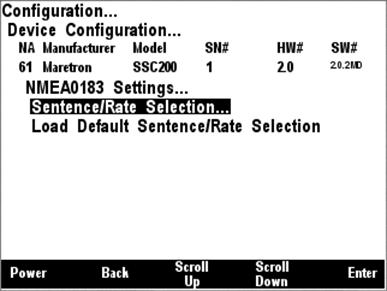
Figure 29 – SSC200 NMEA 0183 Setting options
The NMEA 0183 interface is a very low bandwidth interface. The SSC200 is capable of transmitting a wide variety of NMEA 0183 sentences, and can exceed the bandwidth of the NMEA 0183 interface if all sentences are transmitted at maximum rates, causing lost data in NMEA 0183 multiplexers or on the SSC200 interface itself.
It is important, therefore, to limit the types of NMEA 0183 sentences transmitted only to those that are necessary for other products which are connected to the NMEA 0183 interface. Figure 30 below shows the SSC200 NMEA 0183 Settings Periodic Rate Setup menu. In this menu, you can selectively enable and disable the different NMEA 0183 sentences that the SSC200 can transmit, and you can program the transmission interval for the enabled sentences. In the figure, you can see that the HDG and ROT sentences will be transmitted every 0.1 second (10 times/second), the ATT sentence will be transmitted once per second, and the HDM and HDT sentences are disabled.
The last line in the menu enables you to program the lifetime of the variation data received by the SSC200. In the figure, you can see that the “Variation Time” has been programmed to 5.0 seconds. This means that if the compass has not received magnetic variation for five seconds, it will no longer transmit true heading data, as the variation data it has received is now expired. The default value of 5.0 seconds should be adequate for the majority of applications, but it may need to be increased for variation sources that transmit less frequently.

Figure 30 – SSC200 NMEA 0183 Periodic Rate Menu
Figure 31 below shows the last menu option, which will reset the NMEA 0183 sentence enable/disable status, along with transmission intervals and variation time, to their factory default settings.
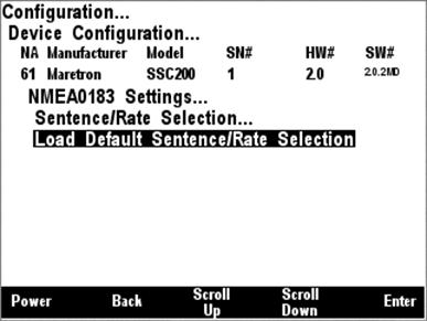
Figure 31 – SSC200 Load Default Periodic Rate Menu Selection
5.2.2.3.2 Maretron DST100 Configuration
5.2.2.3.2.1 Trip Log Resetting
The DSM200 is capable of clearing the trip log counter
within a DST100 depth/speed/temperature transducer. You zero the trip log by
pressing the Enter key (![]() ) with the “Trip Log” menu
item selected which result in the screen shown Figure 32. Pressing the accept (
) with the “Trip Log” menu
item selected which result in the screen shown Figure 32. Pressing the accept (![]() ) key while the “Reset” menu item is selected will complete the
operation
) key while the “Reset” menu item is selected will complete the
operation
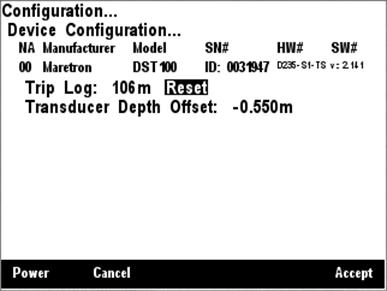
Figure 32 – Resetting the DST100 Trip Distance Log
5.2.2.3.2.2 Transducer Depth Offset Calibration
The DSM200 can set the transducer depth offset parameter in a DST100 depth/speed/temperature transducer. If you are interested in the actual water depth (as opposed to the depth beneath the keel), then you should program a positive value equal to the distance from the waterline to the depth of the DST100. The DSM200 will then add the measured depth of the water (as seen by the DST100) to the programmed offset value to produce the total water depth. If you are interested in the depth of water beneath the keel, then you should program a negative value equal to the distance between the DST100 and the bottom of the keel. The DSM will then subtract the programmed offset from the measured depth of the water (as seen by the DST100) showing you the depth of water beneath the keel.
You program the transducer depth offset by pressing the
Enter key (![]() ) with the “Transducer Depth
Offset” menu item selected which results in the screen shown in Figure 33.
) with the “Transducer Depth
Offset” menu item selected which results in the screen shown in Figure 33.

Figure 33 – Setting the Transducer Depth Offset in a DST100
With the offset value
highlighted, you can change the offset by using the Increase and Decrease keys (![]() or
or
![]() ).
Once you have selected the desired offset, push the Enter key (
).
Once you have selected the desired offset, push the Enter key (![]() ) to complete the transducer depth offset calibration. This
procedure actually programs the offset value into the DST100 such that all
displays subsequently receive the offset information. This means you don’t have
to program multiple displays each with the corresponding offset information as
the information is stored at a single place (at the source).
) to complete the transducer depth offset calibration. This
procedure actually programs the offset value into the DST100 such that all
displays subsequently receive the offset information. This means you don’t have
to program multiple displays each with the corresponding offset information as
the information is stored at a single place (at the source).
5.2.2.3.3 Maretron GPS100 Configuration
The GPS100 has several different programmable parameters that are configurable by the DSM200 display. Normally, it is not necessary to configure the GPS100 although there may be some circumstances where configuration is desirable. The following sections describe the different configuration modes including the “Restore Factory Defaults” configuration, which allows you to return the GPS100 to the factory settings.
5.2.2.3.3.1 SBAS (WAAS) Enable/Disable
The DSM200 is capable of enabling or disabling the SBAS
(WAAS) function on a Maretron GPS100 GPS Antenna/Receiver. You can change this
setting by pressing the Enter key (![]() ) with the “SBAS:
WAAS,EGNOS,MSAS” menu item selected which causes the screen shown in Figure 34 to be displayed.
) with the “SBAS:
WAAS,EGNOS,MSAS” menu item selected which causes the screen shown in Figure 34 to be displayed.

Figure 34 – Configuring SBAS on a GPS100
The allowable option for SBAS configuration are either “Disable” which causes the GPS100 not to use SBAS satellites, or “Enable” which causes the GPS100 to use SBAS satellites for developing a position fix.
5.2.2.3.3.2 GPS Mode Setting
The DSM200 is capable of setting the minimum operating
mode on a Maretron GPS100 GPS Antenna/Receiver. You can choose this setting by
pressing the Enter key (![]() ) with the “GPS Mode” menu
item selected which causes the screen shown in Figure 35 to be displayed.
) with the “GPS Mode” menu
item selected which causes the screen shown in Figure 35 to be displayed.

Figure 35 – Configuring GPS Operating Mode on a GPS100
The allowable options for GPS Mode are “1D” which allows the GPS to report data when only a one-dimensional fix (time only) or better is obtained; “2D”, which allows the GPS to report data only when a two-dimensional fix or better is obtained; “3D”, which allows the GPS to report data only when a three-dimensional fix or better is obtained, or “Auto” (default), which allows the GPS to report any available data, regardless of the quality of the fix.
5.2.2.3.3.3 Elevation Mask
The DSM200 is capable of setting the Elevation Mask on a
Maretron GPS100 GPS Antenna/Receiver. You can choose this setting by pressing
the Enter key (![]() ) with the “Elevation Mask”
menu item selected which causes the screen shown in Figure 36 to be displayed.
) with the “Elevation Mask”
menu item selected which causes the screen shown in Figure 36 to be displayed.
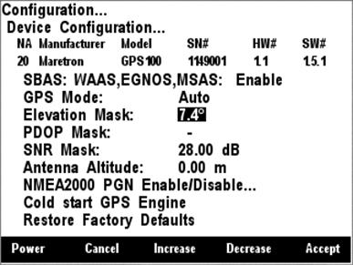
Figure 36 – Configuring Satellite Elevation Mask on a GPS100
The allowable values for Elevation Mask are between -90° and 90°. This number represents the elevation of a satellite above the horizon. Satellites with 0° elevation are at the horizon, while satellites with 90° elevation are directly overhead. The GPS will exclude satellites with an elevation lower than the value of this parameter from the position solution.
5.2.2.3.3.4 PDOP Mask
The DSM200 is capable of setting the PDOP Mask on a
Maretron GPS100 GPS Antenna/Receiver. You can choose this setting by pressing
the Enter key (![]() ) with the “PDOP Mask” menu
item selected which causes the screen shown in Figure 37 to be displayed.
) with the “PDOP Mask” menu
item selected which causes the screen shown in Figure 37 to be displayed.
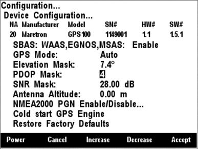
Figure 37 – Configuring PDOP Mask on a GPS100
The allowable values for PDOP Mask are between 1 and 20. This number represents the Position Dilution of Precision, which indicates the accuracy of the computed position and is a function of the positions of the received satellites. If the PDOP of a given position solution is above the value of this parameter, then the GPS100 will report that no fix is obtained. Disabling the PDOP Mask by setting the value to “-“) will cause the GPS100 to report any position fixes obtained, regardless of the accuracy of the fix.
5.2.2.3.3.5 SNR Mask
The DSM200 is capable of setting the SNR (Signal to Noise
Ratio) Mask on a Maretron GPS100 GPS Antenna/Receiver. You choose this setting
by pressing the Enter key (![]() ) with the “SNR Mask” menu
item selected which results in the screen shown in Figure 38.
) with the “SNR Mask” menu
item selected which results in the screen shown in Figure 38.

Figure 38 – Configuring SNR Mask on a GPS100
The allowable values for the SNR Mask are between 1 dB and 60 dB. This number represents the signal to noise ratio of a satellite’s signal as received by the GPS100. Higher numbers indicate a better quality signal. The GPS will exclude satellites with signal to noise ratios lower than the value of this parameter from the position solution.
5.2.2.3.3.6 Antenna Altitude
The DSM200 is capable of setting the antenna altitude on
a Maretron GPS100 GPS Antenna/Receiver. You can choose this setting by pressing
the Enter key (![]() ) with the “Antenna Altitude”
menu item selected which causes the screen shown in Figure 39 to be displayed.
) with the “Antenna Altitude”
menu item selected which causes the screen shown in Figure 39 to be displayed.

Figure 39 – Configuring Antenna Altitude on a GPS100
The allowable values for the Antenna Altitude are between -100m and 100m. This number represents the altitude or the GPS100, and is used to improve the quality of the position fix if only a two-dimensional fix is obtainable. If a three-dimensional position fix is obtainable, this value is not used.
5.2.2.3.3.7 NMEA 2000® PGN Enable/Disable
The GPS100 GPS Antenna/Receiver
transmits several different messages, which can be turned on or turned off by
the DSM200 display. Pressing the Enter key (![]() ) with
NMEA2000® PGN Enable/Disable” menu item selected causes the DSM200
to display the screen shown in Figure 40.
) with
NMEA2000® PGN Enable/Disable” menu item selected causes the DSM200
to display the screen shown in Figure 40.
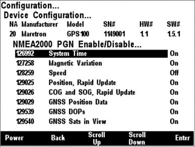
Figure 40 – Maretron GPS100 NMEA 2000® PGN Enable/Disable Screen
You can enable or disable specific transmissions by scrolling (![]() or
or
![]() )
through the different transmitted messages and pressing the Enter key (
)
through the different transmitted messages and pressing the Enter key (![]() ) on the message to be configured. Select whether you want the
message to be transmitted (“On”) or disabled (“Off”) using the Scroll Up (
) on the message to be configured. Select whether you want the
message to be transmitted (“On”) or disabled (“Off”) using the Scroll Up (![]() ) or Scroll Down (
) or Scroll Down (![]() ) keys followed by the Enter
key (
) keys followed by the Enter
key (![]() ).
).
5.2.2.3.3.8 Cold Start GPS
The DSM200 is capable of restarting the GPS algorithm on
a Maretron GPS100 GPS Antenna/Receiver. You can choose this setting by pressing
the Enter key (![]() ) with the “Cold Start” menu
item selected which causes the screen shown in Figure 41 to be displayed. This
will cause the GPS100 to discard all position and satellite data and compute a
position fix.
) with the “Cold Start” menu
item selected which causes the screen shown in Figure 41 to be displayed. This
will cause the GPS100 to discard all position and satellite data and compute a
position fix.
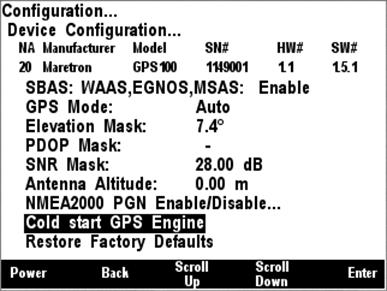
Figure 41 – Performing a Cold Start of the GPS100
5.2.2.3.3.9 Restore Factory Defaults
The DSM200 is capable of restoring all programmable
settings on a Maretron GPS100 GPS Antenna/Receiver to the factory default
condition. You can choose this setting by pressing the Enter key (![]() ) with the “Restore Factory Defaults” menu item selected which
causes the screen shown in Figure 42 to be displayed. This will cause the
GPS100 to set all programmable settings to the factory default condition.
) with the “Restore Factory Defaults” menu item selected which
causes the screen shown in Figure 42 to be displayed. This will cause the
GPS100 to set all programmable settings to the factory default condition.
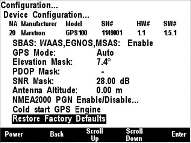
Figure 42 – Restoring Factory Defaults on the GPS100
5.2.2.3.4 Maretron USB100 Configuration
Maretron USB100 gateways on the network may be configured using the DSM200. The USB100 configuration menu is shown in Figure 43 below. There are two configurable items for the USB100: “Remote Device Selection”, and “Copy device selection from local display”.
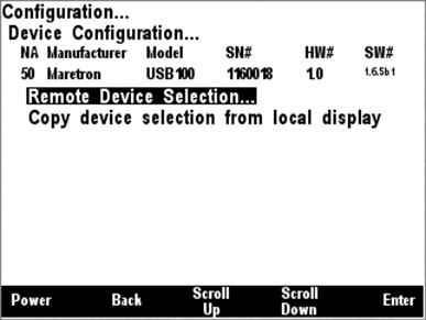
Figure 43 – USB100 Configuration Menu
5.2.2.3.4.1 Remote Device Selection
Like the DSM200, the Maretron USB100 NMEA 2000® to NMEA 0183 gateway can be configured to select which NMEA 2000® devices are selected for display on the computer attached to the USB interface of the USB100. In this manner, multiple devices of the same type may be used on a NMEA 2000® network in a fail-safe configuration. The USB100 Device Selection Menu for an example network configuration can be seen in Figure 44.
WARNING: Do not select multiple devices of the same type for display. This will result in multiple and possibly conflicting readings.
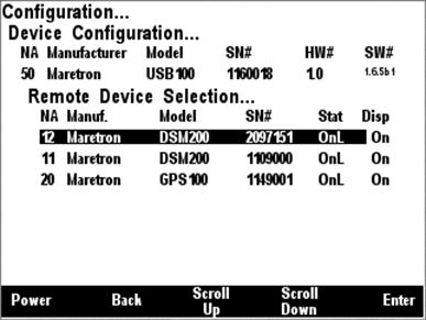
Figure 44 – USB100 Device Selection Menu
The “NA” column of the menu displays the node address the device is using.
The “Manuf” column of the menu displays the manufacturer of the device.
The “Model” column displays the model number of the device.
The “SN#” column displays the serial number of the device, so that any of two or more devices of the same manufacturer and model number may be distinguished from one another.
The “Stat” column indicates whether the device is currently connected to the bus and is responding to queries (“Online”), or has been disconnected from the bus, has lost power, or for some other reason is not responding to queries (“Offline”).
The “Disp” column
indicates whether data from that particular device is accepted for display by
the USB100 (“On”) or that the USB100 ignores data transmitted by this device
(“Off”). By scrolling to the device and pressing the Enter key (![]() ), you may then use the Scroll Up (
), you may then use the Scroll Up (![]() ) and Scroll
Down (
) and Scroll
Down (![]() ) keys to toggle the “Display”
status for this particular device. Once you are satisfied with the state of the
“Display” setting, press the Enter key (
) keys to toggle the “Display”
status for this particular device. Once you are satisfied with the state of the
“Display” setting, press the Enter key (![]() ) to accept
the setting.
) to accept
the setting.
The USB100 will retain information on devices that have been removed from the bus or powered down (“Offline”) so that when they are placed back on the bus, they will assume their prior “Display” setting.
5.2.2.3.4.2 Copy device selection from local display
Since it is normally desirable for an attached computer to display the same sensors as a DSM200, it is possible to copy the device selection settings from a DSM200 unit to a USB100. In this way, it is possible to make all device selection changes on a single DSM200 unit and then quickly and conveniently duplicate these new device selection settings on USB100 units attached to the network. Figure 45 below shows this menu item highlighted.
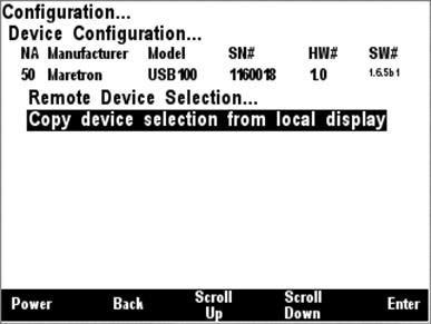
Figure 45 – USB100 Copy Device Selection Menu Item
After you select this menu item and press Enter, the device selection settings from this DSM200 unit will be copied to the selected USB100 unit.
5.2.2.3.5 Maretron DSM200 Configuration
Many configuration settings on remotely-located DSM200 units may be configured from a DSM200. The Remote DSM200 configuration menu is shown in Figure 46 below. There are three configurable items on the DSM200: “Remote Device Selection”, “Copy device selection from local display”, and “Copy favorite settings from local display”.
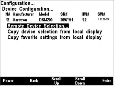
Figure 46 – Remote DSM200 Configuration Menu
5.2.2.3.5.1 Remote Device Selection
A DSM200 unit can be used to configure other DSM200 units on the network to select which NMEA 2000® devices are selected for display on those DSM200 units. In this manner, multiple devices of the same type may be used on a NMEA 2000® network in a fail-safe configuration. For example, a certain compass unit may be selected for display on the remote DSM200. The Remote DSM200 Device Selection Menu for an example network configuration can be seen in Figure 47 below.
WARNING: Do not select multiple devices of the same type for display. This will result in multiple and possibly conflicting readings.

Figure 47 – Remote DSM200 Device Selection Menu
The “NA” column of the menu displays the node address the device is using.
The “Manuf.” column of the menu displays the manufacturer of the device.
The “Model” column displays the model number of the device.
The “SN#” column displays the serial number of the device, so that any of two or more devices of the same manufacturer and model number may be distinguished from one another.
The “Stat” column indicates whether the device is currently connected to the bus and is responding to queries (“Online”), or has been disconnected from the bus, has lost power, or for some other reason is not responding to queries (“Offline”).
The “Disp” column
indicates whether data from that particular device is accepted for display by
the remote DSM200 (“On”) or that the remote DSM200 ignores data transmitted by
this device (“Off”). By scrolling to the device and pressing the Enter key (![]() ), you may then use the Scroll Up (
), you may then use the Scroll Up (![]() ) and Scroll
Down (
) and Scroll
Down (![]() ) keys to toggle the “Display”
status for this particular device. Once you are satisfied with the state of the
“Display” setting, press the Enter key (
) keys to toggle the “Display”
status for this particular device. Once you are satisfied with the state of the
“Display” setting, press the Enter key (![]() ) to accept
the setting.
) to accept
the setting.
The remote DSM200 will retain information on devices that have been removed from the bus or powered down (“Offline”) so that when they are placed back on the bus, they will assume their prior “Display” setting.
5.2.2.3.5.2 Copy device selection from local display
Since it is normally desirable for all DSM200 units on a network to display the same sensors, it is possible to copy the device selection settings from a DSM200 unit to a remotely located DSM200. In this way, it is possible to make all device selection changes on a single DSM200 unit and then quickly and conveniently duplicate these new device selection settings on other DSM200 units attached to the network. Figure 48 below shows this menu item highlighted.

Figure 48 – Remote DSM200 Copy Device Selection Menu Item
After you select this menu item and press Enter, the device selection settings from this DSM200 unit will be copied to the selected remote DSM200 unit.
5.2.2.3.5.3 Copy favorite settings from local display
It is also possible to copy the favorite screen settings from one DSM200 to a remote DSM200 unit. This menu item can be seen selected in Figure 49 below.
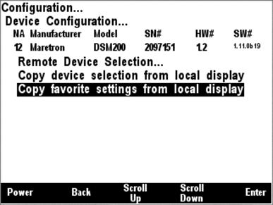
Figure 49 – Copy favorite settings from local display Menu Item
By selecting this menu item and pressing Enter, all of the favorite screen settings will be copied from the local DSM200 to the selected remote DSM200 unit. After copying favorite screen settings, it is necessary to restart the remote unit. A screen, which can be seen in Figure 50 below will appear indicating that favorite settings have been successfully transferred to the remote DSM200 and that the remote DSM200 must be restarted to complete the operation. Press Enter to restart the remote DSM200 unit, complete the favorite settings transfer operation, and return to the previous menu selection.
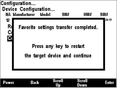
Figure 50 – Favorite Settings Transfer Completion Screen
5.2.2.3.6 Maretron TLA100 Configuration
Maretron TLA100 tank level adapters on the network may be configured using the DSM200. The TLA100 configuration menu is shown in Figure 51 below.
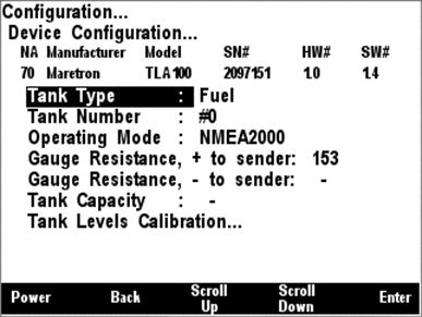
Figure 51 - TLA100 Configuration Menu
5.2.2.3.6.1 Tank Type
The TLA100 can be used in tanks
containing any of a number of different types of fluids. So that
network-connected monitoring devices can determine easily what sort of fluid is
in the monitored tank, the TLA100 must be programmed to indicate the fluid type
it is monitoring. Figure 52 below shows a screen shot of the tank type being
configured. First, use the Scroll Up (![]() ) or Scroll
Down (
) or Scroll
Down (![]() ) keys to position the
highlighted cursor over “Tank Type”, then press the Enter key (
) keys to position the
highlighted cursor over “Tank Type”, then press the Enter key (![]() ) to move the highlight to the tank type data itself. Now, use the
Scroll Up (
) to move the highlight to the tank type data itself. Now, use the
Scroll Up (![]() ) or Scroll Down (
) or Scroll Down (![]() ) keys to change the tank type data to the type desired. Finally,
press the Enter key (
) keys to change the tank type data to the type desired. Finally,
press the Enter key (![]() ) to confirm the selection and
store the value within the TLA100.
) to confirm the selection and
store the value within the TLA100.
Available tank types are as follows:
- Fuel
- Fresh Water
- Waste Water
- Live Well
- Oil
- Black Water
There are also a number of reserved tank types to accommodate possible future undefined tank types.
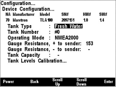
Figure 52 - Configuring the Tank Type
5.2.2.3.6.2 Tank Number
Next, the tank number must be configured. A tank number can have a value between 0 and 15. Each tank of a particular type must have a tank number that is different from all other tanks of the same type. For instance, only one TLA100 on a fuel tank may have tank number equal to “0”. A screenshot of tank number configuration is shown in Figure 53 below.
In order to configure the tank number, use the Scroll Up (![]() ) or Scroll Down (
) or Scroll Down (![]() ) keys to move the highlighted
cursor to “Tank Number”, then press the Enter key (
) keys to move the highlighted
cursor to “Tank Number”, then press the Enter key (![]() ) to move the
cursor over to the tank number value. Use the Scroll Up (
) to move the
cursor over to the tank number value. Use the Scroll Up (![]() ) or
Scroll Down (
) or
Scroll Down (![]() ) keys to select the desired
tank number. Finally, press the Enter key (
) keys to select the desired
tank number. Finally, press the Enter key (![]() ) to confirm
your selection and store the new tank number within the TLA100.
) to confirm
your selection and store the new tank number within the TLA100.
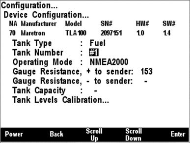
Figure 53 - Configuring the Tank Number
5.2.2.3.6.3 Operating Mode
The TLA100 can be operated in one of two operating modes, depending on the installation.
1) NMEA 2000 (the only thing that is connected to the resistive sender is the TLA100)
2) NMEA 2000 & Analog Gauge (in addition to the TLA100, the resistive sender is also connected to a dual-coil analog gauge).
It is important that this setting be performed correctly in order for the TLA100 to produce correct level measurements. A screenshot showing configuration of the operating mode appears in Figure 54 below.
To configure the operating
mode, use the Scroll Up (![]() ) or Scroll Down (
) or Scroll Down (![]() ) keys to move the highlighted cursor over the “Operating Mode” menu
item, then press the Enter key (
) keys to move the highlighted cursor over the “Operating Mode” menu
item, then press the Enter key (![]() ) to move the highlight over
the operating mode value. Use the Scroll Up (
) to move the highlight over
the operating mode value. Use the Scroll Up (![]() ) or Scroll
Down (
) or Scroll
Down (![]() ) keys to change the operating
mode to the desired value, and finally, press the Entry key to confirm your
selection and store the operating mode within the TLA100.
) keys to change the operating
mode to the desired value, and finally, press the Entry key to confirm your
selection and store the operating mode within the TLA100.
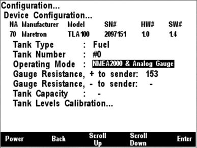
Figure 54 - Configuring the Operating Mode
5.2.2.3.6.4 Gauge Resistance, + to Sender
If the desired operating mode is “NMEA 2000 & Analog Gauge”, the two gauge resistances must be programmed (please refer to the TLA100 User’s Manual for details on how to perform these measurements). A screenshot of the + to sender gauge resistance configuration is shown in Figure 55 below.
To program the + to sender gauge resistance, use the Scroll
Up (![]() ) or Scroll Down (
) or Scroll Down (![]() ) keys to move the highlighted cursor over the “Gauge Resistance, +
to Sender” menu item. Then, press the Enter key (
) keys to move the highlighted cursor over the “Gauge Resistance, +
to Sender” menu item. Then, press the Enter key (![]() ) to move the
highlight over the numerical resistance value. Use the “Increase” and
“Decrease” keys to change the value to the measured resistance value, and
finally, press the Enter key (
) to move the
highlight over the numerical resistance value. Use the “Increase” and
“Decrease” keys to change the value to the measured resistance value, and
finally, press the Enter key (![]() ) to confirm your selection
and store the value within the TLA100.
) to confirm your selection
and store the value within the TLA100.
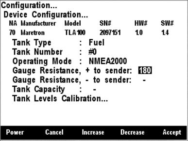
Figure 55 - Configuring the + to Sender Gauge Resistance
5.2.2.3.6.5 Gauge Resistance, - to Sender
If the desired operating mode is “NMEA 2000 & Analog Gauge”, the two gauge resistances must be programmed (please refer to the TLA100 User’s Manual for details on how to perform these measurements). A screenshot of the - to sender gauge resistance configuration is shown in Figure 56 below.
To program the - to sender gauge resistance, use the Scroll
Up (![]() ) or Scroll Down (
) or Scroll Down (![]() ) keys to move the highlighted cursor over the “Gauge Resistance, -
to Sender” menu item. Then, press the Enter key (
) keys to move the highlighted cursor over the “Gauge Resistance, -
to Sender” menu item. Then, press the Enter key (![]() ) to move the
highlight over the numerical resistance value. Use the “Increase” and
“Decrease” keys to change the value to the measured resistance value, and
finally, press the Enter key (
) to move the
highlight over the numerical resistance value. Use the “Increase” and
“Decrease” keys to change the value to the measured resistance value, and
finally, press the Enter key (![]() ) to confirm your selection
and store the value within the TLA100.
) to confirm your selection
and store the value within the TLA100.
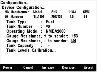
Figure 56 - Configuring the - to Sender Gauge Resistance
5.2.2.3.6.6 Tank Capacity
In order for the TLA100 to produce readings of the amount of fluid remaining in the tank, the tank capacity must be programmed into the TLA100 adapter. Figure 57 below shows a screen shot of the tank capacity being configured.
To program the tank capacity, use the Scroll Up (![]() ) or Scroll Down (
) or Scroll Down (![]() ) keys to move the highlighted
cursor over the “Tank Capacity” menu item. Then, press the Enter key (
) keys to move the highlighted
cursor over the “Tank Capacity” menu item. Then, press the Enter key (![]() ) to move the highlight over the numerical tank capacity value. Use
the “Increase” and “Decrease” keys to change the value to the desired tank
capacity value, and finally, press the Enter key (
) to move the highlight over the numerical tank capacity value. Use
the “Increase” and “Decrease” keys to change the value to the desired tank
capacity value, and finally, press the Enter key (![]() ) to confirm
your selection and store the value within the TLA100.
) to confirm
your selection and store the value within the TLA100.
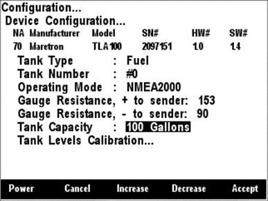
Figure 57 - Configuring the Tank Capacity
After you have pressed the
Enter key (![]() ), a confirmation screen will
appear that warns you that the fluid remaining measurement will change as a
result of this change. Press the Accept key to accept the change and store the
new tank capacity value within the TLA100, or Press the Cancel Key (
), a confirmation screen will
appear that warns you that the fluid remaining measurement will change as a
result of this change. Press the Accept key to accept the change and store the
new tank capacity value within the TLA100, or Press the Cancel Key (![]() ) to cancel the change and leave the old tank capacity programmed into
the TLA100.
) to cancel the change and leave the old tank capacity programmed into
the TLA100.
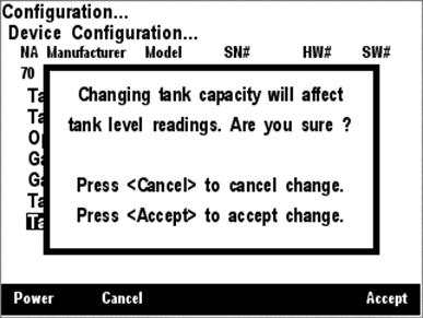
Figure 58 - Tank Capacity Change Confirmation Screen
5.2.2.3.6.7 Tank Levels Calibration
In order for the TLA100 to indicate an accurate tank level, it must know how the resistance of the resistive tank level sender corresponds to the level of fluid in the tank. There are three methods of calibrating the tank level sender:
1) Custom Calibration – use for non-rectangular tanks or non-standard sensors (also, most accurate in any case, but requires more effort)
2) Set to American Standard (240-33 ohm) – use for rectangular tanks using a tank level sender with the standard American resistance range (240 ohms at full, 33 ohms at empty).
3) Set to European Standard (0-180 ohm) – use for rectangular tanks using a tank level sender with the standard European resistance range (0 ohms at full, 180 ohms at empty).
5.2.2.3.6.8 Custom Calibration
The Custom Calibration setting will provide the most accurate tank level readings under any circumstances, but it requires that you go through a process in which you gradually fill the tank, stopping periodically to input the current fluid level. The TLA100 will measure the sender resistance at each point and create a custom calibration map which relates the resistance of the sender with the fluid levels. Figure 59 below shows a screenshot of the DSM200 with the Custom Calibration option highlighted.
Custom calibration is necessary for non-rectangular tanks and for non-standard values of resistances for tank level senders.
To perform custom calibration of
the tank level sender, use the Scroll Up (![]() ) or Scroll
Down (
) or Scroll
Down (![]() ) keys to move the highlighted
cursor over the “Custom Calibration…” menu item. Then, press the Enter key (
) keys to move the highlighted
cursor over the “Custom Calibration…” menu item. Then, press the Enter key (![]() ) to confirm your selection and begin the calibration process.
) to confirm your selection and begin the calibration process.
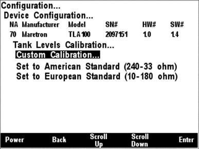
Figure 59 - Performing Custom Calibration of the Tank Level Adapter
The first
step in custom calibration of the tank level sender is to provide an estimated
capacity of the tank. This estimated capacity must be within +/- 25% of the
actual capacity. To set the estimated tank capacity, use the arrow keys to
adjust the displayed value until the desired value is shown. Then, press the
Accept key to confirm your selection and continue with the calibration
process. If you desire to stop the calibration process, pressing the Abort Key
(![]() ) will end the process and return you to the Tank Levels Calibration
menu.
) will end the process and return you to the Tank Levels Calibration
menu.
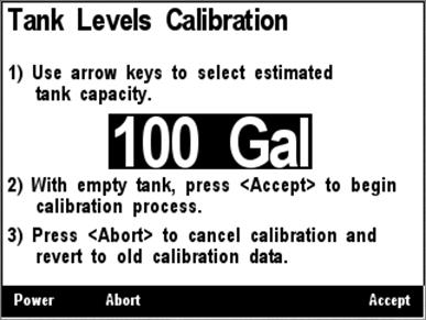
Figure 60 - Tank Levels Calibration Capacity Estimation
The next step in the calibration process is to fill the tank and indicate the volume of fluid in the tank at various points while filling the tank. This process should be started with an empty tank. You only need to indicate two calibration points for a rectangular tank, and can use up to 16 calibration points for a tank with a more complex shape. Figure 61 shows a screenshot of the first calibration step. Enter the first calibration point with an empty tank (0.0 Gallons/liters) by pressing the Accept key. The “Current Point” highlight will advance to the next point.
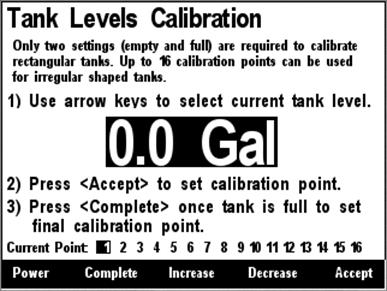
Figure 61 - Empty Level Calibration
Each time you press Accept during this process and after the Current Point highlight advances, put more fluid into the tank, and note the total volume of fluid pumped into the tank at this point. Use the Increase and Decrease keys to set the current tank level to the appropriate value, and then press the Accept key to store the current calibration point and advance to the next calibration point. Figure 62 shows a screenshot of these intermediate calibration points.
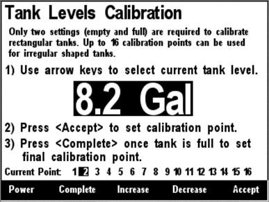
Figure 62 - Intermediate Level Calibration
Once the tank is completely full, instead of pressing the Accept key to store the current calibration point, press the Complete key. This will complete the calibration process and will also adjust the tank capacity to the currently indicated level. Figure 63 below shows the calibration screen at the last point with the full tank level (and thus the tank capacity) set to 101 gallons.
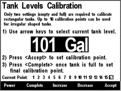
Figure 63 - Full Level Calibration
After you press accept, a confirmation screen will appear showing completion of the calibration process and the new tank capacity value. A screenshot of this calibration screen is shown below in Figure 64.
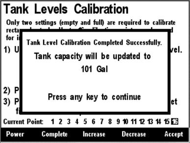
Figure 64 - Custom Tank Level Calibration Confirmation Screen
5.2.2.3.6.9 American Standard Sender Calibration
If you have a rectangular tank,
and a sender with the standard American resistance range (240 ohms full, 33
ohms empty), and you know the capacity of the tank, you can easily calibrate
the sender by using the “Set to American Standard (240-33 ohm)” menu item. Figure 65 below shows this option highlighted. Use the Scroll Up (![]() ) or
Scroll Down (
) or
Scroll Down (![]() ) keys to move the highlight
over this menu item, and then press the Enter key (
) keys to move the highlight
over this menu item, and then press the Enter key (![]() ) to write
the calibration values within the TLA100 and complete the calibration process.
) to write
the calibration values within the TLA100 and complete the calibration process.
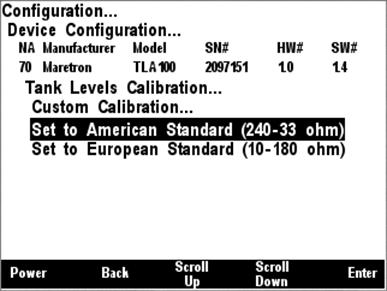
Figure 65 - American Standard Sender Calibration
5.2.2.3.6.10 European Standard Sender Calibration
If you have a rectangular tank,
and a sender with the standard European resistance range (0 ohms full, 180 ohms
empty), and you know the capacity of the tank, you can easily calibrate the
sender by using the “Set to European Standard (0-180 ohm)” menu item. Figure 66 below shows this option highlighted. Use the Scroll Up (![]() ) or
Scroll Down (
) or
Scroll Down (![]() ) keys to move the highlight
over this menu item, and then press the Enter key (
) keys to move the highlight
over this menu item, and then press the Enter key (![]() ) to store
the calibration values within the TLA100 and complete the calibration process.
) to store
the calibration values within the TLA100 and complete the calibration process.
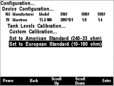
Figure 66 - European Standard Sender Calibration
5.2.2.3.7 RAA100 Configuration
Maretron RAA100 rudder angle adapters on the network may be configured using the DSM200. The RAA100 configuration menu is shown in Figure 43 below.
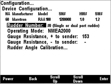
Figure 67 – RAA100 Configuration Menu
5.2.2.3.7.1 Rudder Number
The rudder number must be configured. For a vessel with a single rudder, the number should be set to “0”. For a vessel with two rudders, the port rudder should be set to “0” and the starboard rudder should be set to “1”. Each rudder must have a rudder number that is different from all other rudders. A screenshot of rudder number configuration is shown in Figure 68 below.
In order to configure the rudder
number, use the Scroll Up (![]() ) or Scroll Down (
) or Scroll Down (![]() ) keys to move the highlighted cursor to “Rudder Number”, then press
the Enter key (
) keys to move the highlighted cursor to “Rudder Number”, then press
the Enter key (![]() ) to move the cursor over to
the rudder number value. Use the Scroll Up (
) to move the cursor over to
the rudder number value. Use the Scroll Up (![]() ) or Scroll
Down (
) or Scroll
Down (![]() ) keys to select the desired
rudder number. Finally, press the Enter key (
) keys to select the desired
rudder number. Finally, press the Enter key (![]() ) to confirm
your selection and store the new rudder number within the RAA100.
) to confirm
your selection and store the new rudder number within the RAA100.
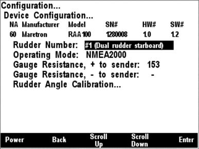
Figure 68 – Setting the Rudder Number
5.2.2.3.7.2 Operating Mode
The RAA100 can be operated in one of two operating modes, depending on the installation.
3) NMEA 2000 (the only thing that is connected to the resistive sender is the RAA100)
4) NMEA 2000 & Analog Gauge (in addition to the RAA100, the resistive sender is also connected to a dual-coil analog gauge).
It is important that this setting be performed correctly in order for the RAA100 to produce correct level measurements. A screenshot showing configuration of the operating mode appears in Figure 69 below.
To configure the operating mode,
use the Scroll Up (![]() ) or Scroll Down (
) or Scroll Down (![]() ) keys to move the highlighted cursor over the “Operating Mode” menu
item, then press the Enter key (
) keys to move the highlighted cursor over the “Operating Mode” menu
item, then press the Enter key (![]() ) to move the highlight over
the operating mode value. Use the Scroll Up (
) to move the highlight over
the operating mode value. Use the Scroll Up (![]() ) or Scroll
Down (
) or Scroll
Down (![]() ) keys to change the operating
mode to the desired value, and finally, press the Entry key to confirm your
selection and store the operating mode within the RAA100.
) keys to change the operating
mode to the desired value, and finally, press the Entry key to confirm your
selection and store the operating mode within the RAA100.

Figure 69 – Setting the Operating Mode
5.2.2.3.7.3 Gauge Resistance, + to Sender
If the desired operating mode is “NMEA 2000 & Analog Gauge”, the two gauge resistances must be programmed (please refer to the RAA100 User’s Manual for details on how to perform these measurements). A screenshot of the + to sender gauge resistance configuration is shown in Figure 70 below.
To program the + to sender gauge
resistance, use the Scroll Up (![]() ) or Scroll Down (
) or Scroll Down (![]() ) keys to move the highlighted cursor over the “Gauge Resistance, +
to Sender” menu item. Then, press the Enter key (
) keys to move the highlighted cursor over the “Gauge Resistance, +
to Sender” menu item. Then, press the Enter key (![]() ) to move the
highlight over the numerical resistance value. Use the “Increase” and
“Decrease” keys to change the value to the measured resistance value, and
finally, press the Enter key (
) to move the
highlight over the numerical resistance value. Use the “Increase” and
“Decrease” keys to change the value to the measured resistance value, and
finally, press the Enter key (![]() ) to confirm your selection
and store the value within the RAA100.
) to confirm your selection
and store the value within the RAA100.
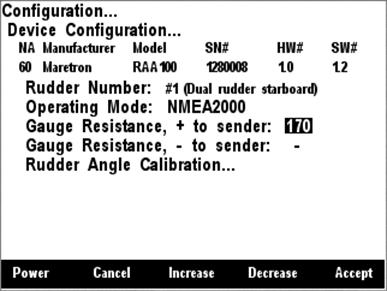
Figure 70 – Setting the + to Sender Gauge Resistance
5.2.2.3.7.4 Gauge Resistance, - to Sender
If the desired operating mode is “NMEA 2000 & Analog Gauge”, the two gauge resistances must be programmed (please refer to the RAA100 User’s Manual for details on how to perform these measurements). A screenshot of the - to sender gauge resistance configuration is shown in Figure 71 below.
To program the - to sender gauge
resistance, use the Scroll Up (![]() ) or Scroll Down (
) or Scroll Down (![]() ) keys to move the highlighted cursor over the “Gauge Resistance, -
to Sender” menu item. Then, press the Enter key (
) keys to move the highlighted cursor over the “Gauge Resistance, -
to Sender” menu item. Then, press the Enter key (![]() ) to move the
highlight over the numerical resistance value. Use the “Increase” and
“Decrease” keys to change the value to the measured resistance value, and
finally, press the Enter key (
) to move the
highlight over the numerical resistance value. Use the “Increase” and
“Decrease” keys to change the value to the measured resistance value, and
finally, press the Enter key (![]() ) to confirm your selection
and store the value within the RAA100.
) to confirm your selection
and store the value within the RAA100.

Figure 71 – Setting the – to Sender Gauge Resistance
5.2.2.3.7.5 Rudder Sender Calibration
In order for the RAA100 to indicate an accurate rudder angle, it must know how the resistance of the resistive rudder angle sender corresponds to the rudder angle. There are three methods of calibrating the rudder angle sender:
1) Custom Calibration – use in most cases
2) Set to American Standard (240-33 ohm) – use for rudders using a rudder angle sender with the standard American resistance range (240 ohms at full port 45°, 33 ohms at full starboard 45°).
3) Set to European Standard (0-180 ohm) – use for rudders using a rudder angle sender with the standard European resistance range (0 ohms at full port 45°, 180 ohms at full starboard 45°).
4) Custom Calibration - The Custom Calibration setting will provide the most accurate rudder angle readings under any circumstances, but it requires that you go through a process in which you set the rudder to full port, then center, and then full starboard, each time indicating the angle of the rudder to the DSM200. The RAA100 will measure the sender resistance at each point and create a custom calibration map which relates the resistance of the sender with the rudder angle. Figure 73 below shows a screenshot of the DSM200 with the Custom Calibration option highlighted.
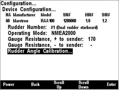
Figure 72 – Rudder Angle Calibration Selection
5.2.2.3.7.6 Custom Calibration
Custom calibration is necessary for non-standard values of resistances for rudder angle senders and for rudders with maximum port and starboard angles of anything other then 45°.
To perform custom calibration of
the rudder angle sender, use the Scroll Up (![]() ) or Scroll
Down (
) or Scroll
Down (![]() ) keys to move the highlighted
cursor over the “Custom Calibration…” menu item. Then, press the Enter key (
) keys to move the highlighted
cursor over the “Custom Calibration…” menu item. Then, press the Enter key (![]() ) to confirm your selection and begin the calibration process. Figure 73 shows the DSM200 with the Custom Rudder Calibration menu item highlighted.
) to confirm your selection and begin the calibration process. Figure 73 shows the DSM200 with the Custom Rudder Calibration menu item highlighted.
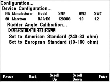
Figure 73 – Custom Rudder Angle Calibration
The first
step in the custom rudder angle sender calibration process is to turn the wheel
hard over to starboard, and to measure the angle or the rudder (angle from
center) with a protractor or other instrument. Use the Increase and Decrease
keys until the highlighted rudder angle value is at the measured value, and
then press Enter to accept the value and store it within the RAA100. Figure 74 shows a screenshot of the starboard rudder calibration screen. You may also
press the Abort Key (![]() ) to end the calibration process.
) to end the calibration process.
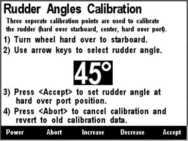
Figure 74 – Starboard Rudder Angle Calibration
The second
step in the custom rudder angle sender calibration process is to turn the wheel
so that the rudder is centered as much as possible. Next, press Enter to
accept the value and store it within the RAA100. Figure 75 shows a screenshot
of the center rudder calibration screen. You may also press the Abort Key (![]() ) to end the calibration process.
) to end the calibration process.
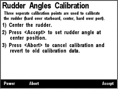
Figure 75 – Center Rudder Angle Calibration
The third
step in the custom rudder angle sender calibration process is to turn the wheel
hard over to port, and to measure the angle or the rudder (angle from center)
with a protractor or other instrument. Use the Increase and Decrease keys
until the highlighted rudder angle value is at the measured value, and then
press Enter to accept the value and store it within the RAA100. Figure 74 shows a screenshot of the starboard rudder calibration screen. You may also
press the Abort Key (![]() ) to end the calibration process.
) to end the calibration process.
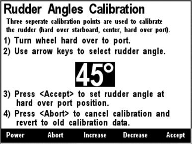
Figure 76 – Port Rudder Angle Calibration
Once you have accepted the port rudder angle value, a confirmation screen appears indicating that the rudder angle calibration has been successfully completed. Figure 77 below shows a screenshot of this confirmation screen.
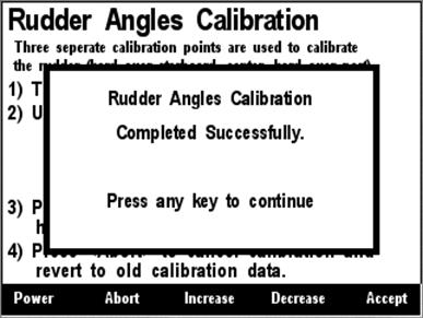
Figure 77 – Custom Rudder Calibration Confirmation Screen
5.2.2.3.7.7 American Standard Sender Calibration
If you have a rudder angle sender
with the standard American resistance range (240 ohms full port 45°, 33 ohms
full starboard 45°) you can easily calibrate the sender by using the “Set to
American Standard (240-33 ohm)” menu item. Figure 78 below shows this option
highlighted. Use the Scroll Up (![]() ) or Scroll Down (
) or Scroll Down (![]() ) keys to move the highlight over this menu item, and then press the
Enter key (
) keys to move the highlight over this menu item, and then press the
Enter key (![]() ) to store the calibration
values within the RAA100 and complete the calibration process.
) to store the calibration
values within the RAA100 and complete the calibration process.
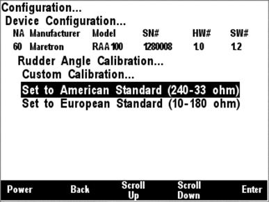
Figure 78 – Setting the Rudder Angle Sender to American Standard
5.2.2.3.7.8 American Standard Sender Calibration
If you have a rudder angle sender
with the standard American resistance range (0 ohms full port 45°, 180 ohms
full starboard 45°) you can easily calibrate the sender by using the “Set to
European Standard (0-180 ohm)” menu item. Figure 79 below shows this option
highlighted. Use the Scroll Up (![]() ) or Scroll Down (
) or Scroll Down (![]() ) keys to move the highlight over this menu item, and then press the
Enter key (
) keys to move the highlight over this menu item, and then press the
Enter key (![]() ) to store the calibration
values within the RAA100 and complete the calibration process.
) to store the calibration
values within the RAA100 and complete the calibration process.
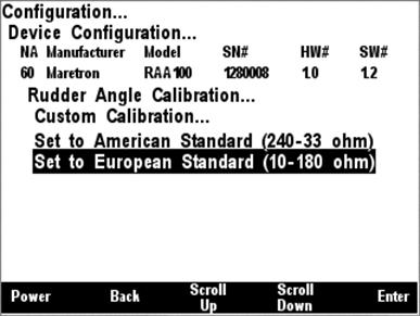
Figure 79 - Setting the Rudder Angle Sender to European Standard
5.2.2.3.8 WSO100 Calibration
The DSM200 is capable of performing configuration of the WSO100 Wind/Weather Sensor. Figure 80 below shows a screenshot of the WSO100 configuration menu.
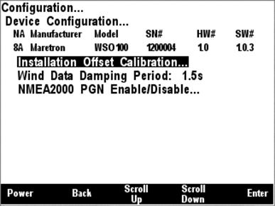
Figure 80 - WSO100 Configuration Menu
5.2.2.3.8.1 Installation Offset Calibration
The WSO100 comes from the factory with a preset orientation, so that mounting it with the orientation marks facing the bow of the vessel, the sensor will read 0° apparent wind angle when the vessel is sailing directly into the wind (please refer to the WSO100 User’s Manual for details).
However, the WSO100 can be installed in any orientation with respect to the vessel and any misalignment with respect to the factory preset can be easily compensated for using the Installation Offset calibration menu item.
To perform installation offset calibration, use the Scroll
Up (![]() ) or Scroll Down (
) or Scroll Down (![]() ) keys to move the highlighted cursor to the Installation Offset
menu item, and then press the Enter key (
) keys to move the highlighted cursor to the Installation Offset
menu item, and then press the Enter key (![]() ). The
Installation Offset screen then appears, which is shown in Figure
81 below.
). The
Installation Offset screen then appears, which is shown in Figure
81 below.
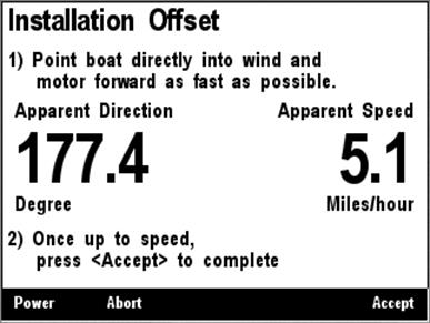
Figure 81 - WSO100 Installation Offset Screen
Turn the vessel directly into the wind and motor forward. When you are satisfied that the apparent wind is directly on the bow of the vessel, press the Accept key to set this angle to read 0° apparent wind on the WSO100.
The WSO100 will only calibrate if the apparent wind speed is greater than 1 meter per second. If the apparent wind speed is lower than this, then an error message will appear, which is shown in Figure 82 below, and the calibration process will be aborted.
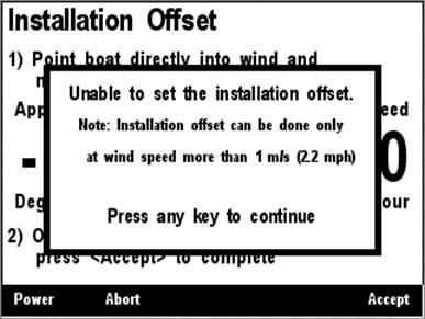
Figure 82 - WSO100 Configuration Aborted Due to Low Wind Speed
If the wind speed is sufficient, then a confirmation screen, shown in Figure 83 below, will appear, indicating that a successful installation offset calibration has completed.
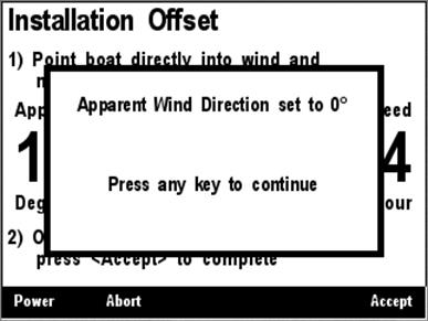
Figure 83 - Installation Offset Success Confirmation Screen
You may instead abort calibration
by pressing the Abort Key (![]() ). If you do this, the
installation offset calibration process will be aborted and a message will
appear noting that this has happened, which appears in Figure 84 below.
). If you do this, the
installation offset calibration process will be aborted and a message will
appear noting that this has happened, which appears in Figure 84 below.
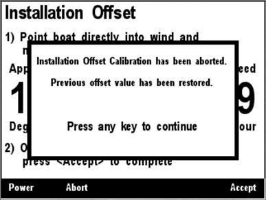
Figure 84 - Installation Offset Abort Confirmation Screen
5.2.2.3.8.2 Wind Data Damping Period
The WSO100 comes from the factory
preset with a damping period of 1.5 seconds, which should be appropriate for
most applications. However, you may use the DSM200 to tune the damping period
to anywhere between 0.1 seconds and 5.0 seconds if you desire. To do this, use
the Scroll Up (![]() ) or Scroll Down (
) or Scroll Down (![]() ) keys to move the highlighted cursor to the Wind Data Damping
Period menu item, then press the Enter key (
) keys to move the highlighted cursor to the Wind Data Damping
Period menu item, then press the Enter key (![]() ) to move the
highlight to the numerical value on the right. This is shown in Figure 85 below. Use the Increase and Decrease keys to adjust the damping period to
the desired value, and then press the Enter key (
) to move the
highlight to the numerical value on the right. This is shown in Figure 85 below. Use the Increase and Decrease keys to adjust the damping period to
the desired value, and then press the Enter key (![]() ) to accept
the value and store it within the WSO100.
) to accept
the value and store it within the WSO100.
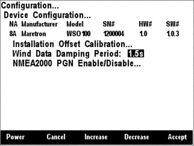
Figure 85 - Setting the Wind Data Damping Period
5.2.2.3.8.3 NMEA 2000 PGN Enable/Disable
From the factory, the WSO100
transmits the Wind Data message (PGN 130306) and the Environmental Parameters
message (PGN 130311). For the vast majority of installations, the factory
setting is appropriate, but if it becomes necessary to disable one of the
transmitted messages from the WSO100, for instance, if you have a separate
thermometer / humidity sensor / barometer on the network, it is possible to do
so with the DSM200. From the WSO100 configuration menu, use the Scroll Up (![]() ) or Scroll Down (
) or Scroll Down (![]() ) keys to move the highlighted
cursor to the NMEA 2000 PGN Enable/Disable menu item, and then press the Entry
key to expand the list of messages transmitted by the WSO100, as shown in Figure 86 below. Use the Scroll Up (
) keys to move the highlighted
cursor to the NMEA 2000 PGN Enable/Disable menu item, and then press the Entry
key to expand the list of messages transmitted by the WSO100, as shown in Figure 86 below. Use the Scroll Up (![]() ) or Scroll Down (
) or Scroll Down (![]() ) keys to highlight the desired message, and then press the Enter
key (
) keys to highlight the desired message, and then press the Enter
key (![]() ) to move the highlight to the
message status on the right. Use the Scroll Up (
) to move the highlight to the
message status on the right. Use the Scroll Up (![]() ) or Scroll
Down (
) or Scroll
Down (![]() ) keys to turn transmission of
the selected message On or Off, as desired, and finally, press the Enter key (
) keys to turn transmission of
the selected message On or Off, as desired, and finally, press the Enter key (![]() ) to accept the change and store the transmit enable/disable status
within the WSO100.
) to accept the change and store the transmit enable/disable status
within the WSO100.

Figure 86 - WSO100 NMEA2000 PGN Enable/Disable Menu
5.2.2.3.9 J2K100 Configuration
The DSM200 is capable of configuring settings on the J1939 to NMEA 2000 Gateway (J2K100). A screenshot of the J2K100 configuration menu is shown in Figure 87 below.
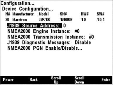
Figure 87 - J2K100 Configuration Menu
5.2.2.3.9.1 J1939 Source Address Configuration
A J1939 engine or transmission has its own source address on the J1939 network, which is different from NMEA 2000 addresses. The J2K100 is capable of serving as a gateway between a single J1939 engine or transmission and the NMEA 2000 network. This setting identifies the J1939 source address of the engine or transmission for which the J2K100 will serve as a gateway.
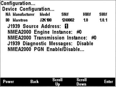
Figure 88 - J1939 Source Address Configuration
To set the J1939 source address,
use the Scroll Up (![]() ) or Scroll Down (
) or Scroll Down (![]() ) keys to move the highlighted cursor to the J1939 Source Address
menu item. Press the Enter key (
) keys to move the highlighted cursor to the J1939 Source Address
menu item. Press the Enter key (![]() ) to move the cursor over to
the source address value on the right, as shown in Figure 88 below. Then, use
the Scroll Up (
) to move the cursor over to
the source address value on the right, as shown in Figure 88 below. Then, use
the Scroll Up (![]() ) or Scroll Down (
) or Scroll Down (![]() ) keys to change the J1939 Source Address value until it matches the
J1939 source address of the engine or transmissions for which you desire this
J2K100 to translate data onto the NMEA 2000 network.
) keys to change the J1939 Source Address value until it matches the
J1939 source address of the engine or transmissions for which you desire this
J2K100 to translate data onto the NMEA 2000 network.
5.2.2.3.9.2 NMEA 2000 Engine Instance Configuration
Each engine on an NMEA 2000
network must have a unique instance identifier, to allow display devices to
distinguish it from other engines on the network. The NMEA 2000 Engine
Instance menu item allows you to configure the engine instance identifier which
will be sent over the NMEA 2000 network along with engine-related NMEA 2000
messages. In order to configure this parameters, use the Scroll Up (![]() ) or Scroll Down (
) or Scroll Down (![]() ) keys to move the highlighted
cursor to the NMEA2000 Engine Instance menu item. Then, press the Enter key (
) keys to move the highlighted
cursor to the NMEA2000 Engine Instance menu item. Then, press the Enter key (![]() ) to move the highlight to the numeric value on the right, as shown
in Figure 89 below.
) to move the highlight to the numeric value on the right, as shown
in Figure 89 below.
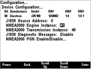
Figure 89 - NMEA2000 Engine Instance Configuration
Use the Scroll Up (![]() ) or Scroll Down (
) or Scroll Down (![]() ) keys to change the value to
the desired value you wish to use as the engine instance identifier, and then
press the Enter key (
) keys to change the value to
the desired value you wish to use as the engine instance identifier, and then
press the Enter key (![]() ) to accept the value and
store it within the J2K100.
) to accept the value and
store it within the J2K100.
5.2.2.3.9.3 NMEA 2000 Transmission Instance Configuration
Each transmission on an NMEA 2000
network must have a unique instance identifier, to allow display devices to
distinguish it from other transmissions on the network. The NMEA 2000
Transmission Instance menu item allows you to configure the transmission
instance identifier which will be sent over the NMEA 2000 network along with
transmission-related NMEA 2000 messages. In order to configure this
parameters, use the Scroll Up (![]() ) or Scroll Down (
) or Scroll Down (![]() ) keys to move the highlighted cursor to the NMEA2000 Transmission
Instance menu item. Then, press the Enter key (
) keys to move the highlighted cursor to the NMEA2000 Transmission
Instance menu item. Then, press the Enter key (![]() ) to move the
highlight to the numeric value on the right, as shown in Figure 90 below.
) to move the
highlight to the numeric value on the right, as shown in Figure 90 below.
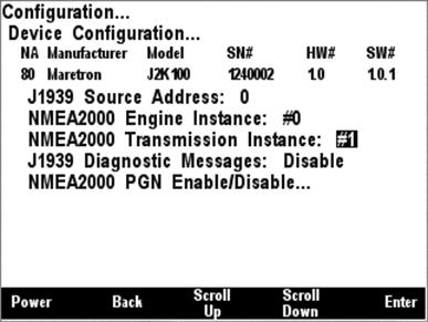
Figure 90 - NMEA2000 Transmission Instance Configuration
Use the Scroll Up (![]() ) or Scroll Down (
) or Scroll Down (![]() ) keys to change the value to
the desired value you wish to use as the engine instance identifier, and then
press the Enter key (
) keys to change the value to
the desired value you wish to use as the engine instance identifier, and then
press the Enter key (![]() ) to accept the value and
store it within the J2K100.
) to accept the value and
store it within the J2K100.
5.2.2.3.9.4 J1939 Diagnostic Messages Configuration
The J2K100 can optionally pass
through J1939 diagnostic messages, used to indicate fault conditions on engines
and transmissions, from the J1939 interface to the NMEA2000 network so that
NMEA 2000 connected displays which can interpret these diagnostic codes. To
change the transmission status of the J1939 diagnostic messages, use the Scroll
Up (![]() ) or Scroll Down (
) or Scroll Down (![]() ) keys to move the highlighted cursor to the J1939 Diagnostic Messages
menu item. Then, press the Enter key (
) keys to move the highlighted cursor to the J1939 Diagnostic Messages
menu item. Then, press the Enter key (![]() ) to move the
highlight to the value field, which displays either Enable or Disable. Use the
Scroll Up (
) to move the
highlight to the value field, which displays either Enable or Disable. Use the
Scroll Up (![]() ) or Scroll Down (
) or Scroll Down (![]() ) keys to change the value to the desired value, and then press the
Enter key (
) keys to change the value to the desired value, and then press the
Enter key (![]() ) to accept the new value and
store it within the J2K100.
) to accept the new value and
store it within the J2K100.
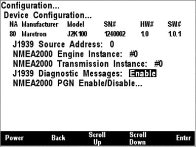
Figure 91 - J1939 Diagnostic Messages Configuration
5.2.2.3.9.5 NMEA 2000 PGN Enable/Disable Configuration
The J2K100 gateway transmits
several different messages, which can be turned on or turned off by the DSM200
display. Pressing the Enter key (![]() ) with NMEA2000®
PGN Enable/Disable” menu item selected causes the DSM200 to display the screen
shown in Figure 92
) with NMEA2000®
PGN Enable/Disable” menu item selected causes the DSM200 to display the screen
shown in Figure 92
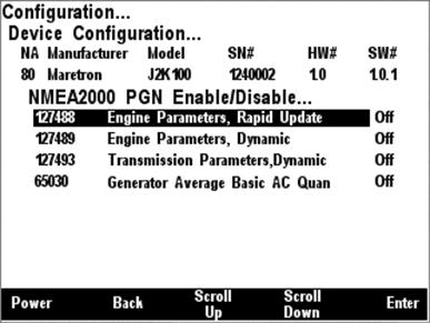
Figure 92 - NMEA2000 PGN Enable/Disable Menu
You can enable or disable specific transmissions by scrolling (![]() or
or
![]() )
through the different transmitted messages and pressing the Enter key (
)
through the different transmitted messages and pressing the Enter key (![]() ) on the message to be configured. Select whether you want the
message to be transmitted (“On”) or disabled (“Off”) using the Scroll Up (
) on the message to be configured. Select whether you want the
message to be transmitted (“On”) or disabled (“Off”) using the Scroll Up (![]() ) or Scroll Down (
) or Scroll Down (![]() ) keys followed by the Enter
key (
) keys followed by the Enter
key (![]() ).
).
5.2.2.3.10 Bennett EP-30 (NMEA1) Trim Tabs Configuration
The DSM200 is capable of configuring Bennett EP-30 Trim Tabs (“NMEA1” NMEA 2000 Trim Tab Indicator Kit). The EP-30 configuration menu is shown below in Figure 93 below, and currently has the single entry “Trim Tabs Calibration…”.
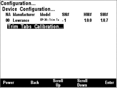
Figure 93 - Bennett EP-30 Trim Tabs Configuration Menu
5.2.2.3.10.1 Trim Tabs Calibration
The Bennett EP-30 (NMEA1) trim tabs calibration opening
screen is shown in Figure 94 below. The first step in calibration is to move
both trim tabs to the full up position, and then press the Accept (![]() ) key to begin the calibration process. You may also elect to abort
the calibration process at this time by pressing the Abort (
) key to begin the calibration process. You may also elect to abort
the calibration process at this time by pressing the Abort (![]() ) key.
) key.
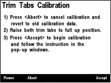
Figure 94 - Bennett EP-30 Trim Tabs Calibration Opening Screen
After you press the Accept (![]() ) key, a
screen, shown in Figure 95 below, appears, instructing you to now lower both
trim tabs to the full down position. It is important that you do this without
stopping in order for the calibration process to succeed.
) key, a
screen, shown in Figure 95 below, appears, instructing you to now lower both
trim tabs to the full down position. It is important that you do this without
stopping in order for the calibration process to succeed.
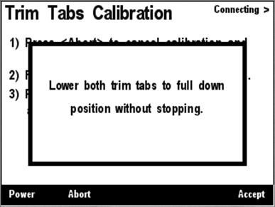
Figure 95 - Bennett EP-30 Intermediate Calibration Screen
After you have lowered both trim tabs to their full down position and a few seconds have elapsed, the screen shown in Figure 96 below should appear, indicating that the calibration of the trim tab sensors has completed successfully. You may now press any key to return to the previous menu.
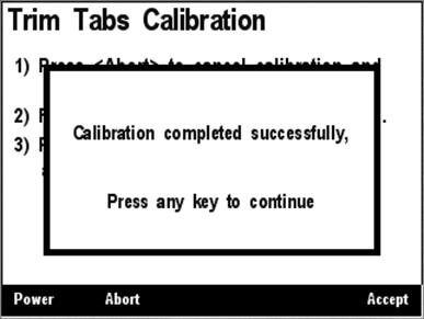
Figure 96 - Bennett EP-30 Calibration Success Message
5.2.3 Display Settings Menu
The display settings menu allows you to change parameters related to display operation.
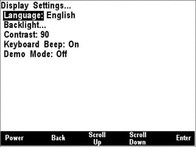
Figure 97 – Display Settings Menu
5.2.3.1 Language
The DSM200 currently supports two languages: English and
Dutch (Nederlands). Support for other languages is planned for future firmware
releases. To change the currently used language, use the Scroll Up (![]() ) or Scroll Down (
) or Scroll Down (![]() ) keys to move the highlight
to the Language menu item, and then press the Enter key (
) keys to move the highlight
to the Language menu item, and then press the Enter key (![]() )
to move the highlight to the language selection on the right. Use the Scroll Up
(
)
to move the highlight to the language selection on the right. Use the Scroll Up
(![]() ) or Scroll Down (
) or Scroll Down (![]() ) keys to change the selection to the desired value, and then press
the Enter key (
) keys to change the selection to the desired value, and then press
the Enter key (![]() ) to confirm your selection.
The DSM200 will then reset itself, after which the selected language will be
used for menus and titles.
) to confirm your selection.
The DSM200 will then reset itself, after which the selected language will be
used for menus and titles.
5.2.3.2 Backlight
The DSM200 has a red LED
backlight. There are three user-programmable lighting levels which may be
cycled through using the Lights key (![]() ) on the DSM200 keypad while the
DSM200 is operating in favorite screens mode. Each time you press the Lights
key (
) on the DSM200 keypad while the
DSM200 is operating in favorite screens mode. Each time you press the Lights
key (![]() ) in favorite screens mode,
the DSM200 backlight will transition between the “Off” state (0% brightness),
the “Low” setting, the “Medium” setting, and the “High” setting. The Backlight
menu allows you to program the “Low”, “Medium”, and “High” brightness levels.
The value that appears next to the appropriate setting is measured in percent
of full brightness. The Backlight menu can be seen in Figure 98 below.
) in favorite screens mode,
the DSM200 backlight will transition between the “Off” state (0% brightness),
the “Low” setting, the “Medium” setting, and the “High” setting. The Backlight
menu allows you to program the “Low”, “Medium”, and “High” brightness levels.
The value that appears next to the appropriate setting is measured in percent
of full brightness. The Backlight menu can be seen in Figure 98 below.
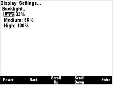
Figure 98 – Backlight Menu
5.2.3.3 Contrast
The DSM200 has user-programmable contrast for the LCD display. The contrast is variable between 0 and 255. You may wish to adjust this number in order allow the DSM200 to be viewed best at a particular angle or operating temperature.

Figure 99 – Setting the Contrast
5.2.3.4 Keyboard Beep
The DSM200 has an annunciator that can be programmed to beep every time a key is pressed. Conversely, the keypad beep may be disabled if desired.
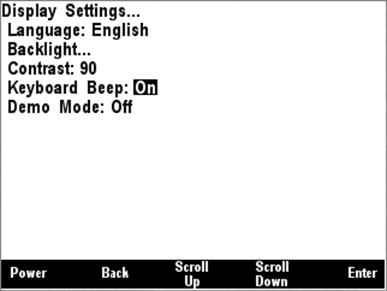
Figure 100 – Setting the Keyboard Beep Option
5.2.3.5 Demo Mode
The DSM200 has a demo mode suited for displaying the capabilities of the unit. It causes the DSM200 to operate in a “simulated data” mode, where the DSM200 will install a set of pre-defined favorite screens and other configuration and will then display only the internally generated simulated data and will ignore any data arriving over the NMEA 2000® bus. While in demo mode, the DSM200 will display a blinking “Demo” indicator in the upper right hand corner of the screen. Programming this option to “On” will cause the DSM200 to enter the demo mode while programming this option for “Off” will cause the DSM200 to return to using data from the NMEA 2000® bus.
WARNING: All data displayed in demo mode is simulated. Do not rely on this data for navigation purposes.
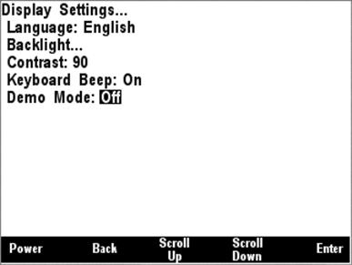
Figure 101 – Setting the Demo Mode
5.2.4 Favorite Screens Mode Setting
The DSM200 supports two methods
of operation in favorites mode: “Auto”, in which the DSM200 automatically
cycles through all favorite screens that have been enabled for Auto mode, and
“Manual”, in which the DSM200 continues to display the currently displayed
favorite screen until you press the Scroll Up (![]() ) or Scroll
Down (
) or Scroll
Down (![]() ) keys, in which the DSM200
will display the next higher or lower numbered favorite screen, respectively,
that is enabled for Manual mode.
) keys, in which the DSM200
will display the next higher or lower numbered favorite screen, respectively,
that is enabled for Manual mode.
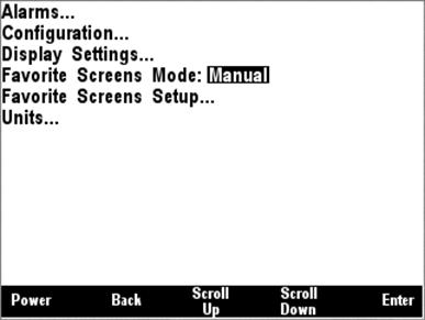
Figure 102 – Setting the Favorite Screens Mode
5.2.5 Favorite Screens Setup Menu
The DSM200 supports the configuration of eight favorite screens. The favorite setup menu allows you to select which of the eight favorite screens you wish to configure.
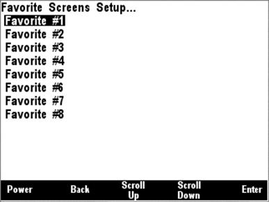
Figure 103 – Favorite Screens Setup Menu
5.2.5.1 Favorite Mode
Once you have selected a favorite screen to configure, you will see the screen shown in Figure 104 with the first menu option “Favorite Mode”. This entry allows you to select in which display method of favorite screens mode this particular favorite screen is enabled. This parameter has four possible settings:
- Off – this favorite screen is disabled and is not displayed
- Auto – this favorite screen is displayed only in Auto mode
- Manual – this favorite screen is displayed only in Manual mode
- Auto/Manual – this favorite screen is displayed ion both Auto and Manual modes
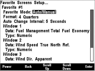
Figure 104 – Setting the Favorite Mode
5.2.5.2 Format
The DSM200 offers many methods and formats of displaying multiple data items at a given time. This parameter is used to program how many data items will appear on this particular favorite screen and in what sizes these items will appear. This parameter has the following settings:
- Full Screen – one parameter will be displayed, taking up the entire screen
- 2/3 Top – 1/3 Bottom – two parameters will be displayed, the first occupying the top 2/3 of the screen and the second occupying the bottom 1/3 of the screen
- 1/3 Top – 2/3 Bottom – two parameters will be displayed, the first occupying the top 1/3 of the screen and the second occupying the bottom 2/3 of the screen
- Half Left – Qtr – Qtr – three parameters will be displayed, the first occupying the left half of the screen, the second occupying the upper right hand corner of the screen and the third occupying the lower right hand corner of the screen
- Qtr – Half – Qtr – three parameters will be displayed, the first occupying the top left hand corner of the screen, the second occupying the upper right hand corner of the screen, and the third occupying the lower right hand corner of the screen
- Half Left/Right – two parameters will be displayed, the first occupying the left half of the screen, and the second occupying the right half of the screen
- Half Top/Bottom – two parameters will be displayed, the first occupying the top half of the screen and the second occupying the bottom half of the screen
- 2 Qtrs – Half Bottom – three parameters will be displayed, the first occupying the upper left hand corner of the screen, the second occupying the upper right hand corner of the screen, and the third occupying the bottom half of the screen
- Half Top – 2 Qtrs – three parameters will be displayed, the first occupying the top of the screen, the second occupying the lower left hand corner of the screen, and the third occupying the lower right hand corner of the screen
- Four Quarters – four parameters will be displayed, the first occupying the upper left hand corner of the screen, the second occupying the upper right hand corner of the screen, the third occupying the lower left hand corner of the screen, and the fourth occupying the lower right hand corner of the screen
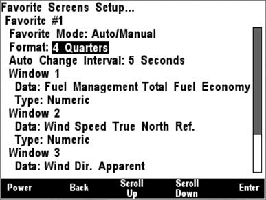
Figure 105 – Setting the Favorite Screen Format
5.2.5.3 Auto Change Interval
In Auto mode, this parameter determines the amount of time this favorite screen is displayed before the DSM200 automatically cycles to the next higher numbered favorite screen. This parameter is programmable to anywhere between 1 second and 180 seconds.

Figure 106 – Setting the Auto Change Interval
5.2.5.4 Window Data
The Window Data section of the
menu allows you to select a particular type of data to be displayed. .
Selecting the data to be displayed is a two-step process. First, press the
Enter key (![]() ) and select the category of
data to be displayed.
) and select the category of
data to be displayed.
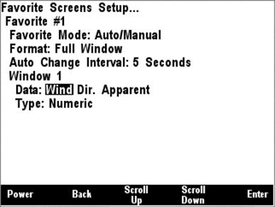
Figure 107 – Selecting the Data Category
Once you select the category, press the Enter key (![]() ) to accept this category, at which time the highlight will move to
the data type field, where you can display the particular data type from the
selected category to be displayed as shown in Figure 108.
) to accept this category, at which time the highlight will move to
the data type field, where you can display the particular data type from the
selected category to be displayed as shown in Figure 108.
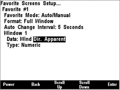
Figure 108 – Selecting the Data to be Displayed
5.2.5.4.1 Type
Once you have selected the particular data item to be displayed, you may select the type of data display to be used for that data item as shown in Figure 109. The available display types vary depending upon the selected data item, but may include any of the following (see Section 6 on page 88 for descriptions of the available display types.
- Numeric (see Section 6.1 on page 88)
- Compass Rose (see Section 6.2 on page 88)
- GPS Status (see Section 6.3 on page 89)
- Gauge (see Section 6.4 on page 90)
- Rolling Road (see Section 6.5 on page 91)
- Line Graph (see Section 6.6 on page 93).
- Weather Screen (see Section 6.7 on page 93)
- Wind Rose (see Section 6.8 on page 94)
- Moon Phase (see Section 6.9 on page 95)
- Trim Tab (see Section 6.10 on page 95)
- Swing Meter (see Section 6.11 on page 96)
- Tank Gauge (see Section 6.12 on page 96)
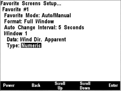
Figure 109 – Setting the Data Type
5.2.6 Units Menu
The Units Menu allows you to set the desired display units for the DSM200. The following sections provide more detail on the individual unit settings.
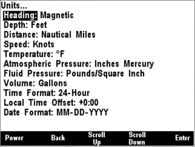
Figure 110 – DSM200 Units Menu
5.2.6.1 Heading
This menu item allows you to select whether heading, course, and bearing information is displayed in true or magnetic measurements. True heading can only be displayed if a variation is available on the NMEA 2000® bus (see Section 5.2.1 on page 16 for instructions on how to configure the Maretron SSC200 compass to transmit magnetic variation).
NOTE: The one exception to the setting of this configuration option is Course Over Ground (COG). COG is always displayed as a true heading, regardless of the setting of the Heading units in this configuration item.
5.2.6.2 Depth
This menu item allows you to select the units to be used for the display of all depth-related information. Units that may be selected are the following:
- Meters
- Fathoms
- Feet
5.2.6.3 Distance
This menu item allows you to select the units to be used for the display of all distance-related information. Units that may be selected are the following:
- Nautical Miles
- km
- Statute Miles
5.2.6.4 Boat Speed
This menu item allows you to select the units to be used for the display of all boat speed-related information. Units that may be selected are the following:
- Knots
- Meters/second
- Miles/hour
- Km/hour
5.2.6.5 Wind Speed
This menu item allows you to select the units to be used for the display of all wind speed-related information. Units that may be selected are the following:
- Knots
- Meters/second
- Miles/hour
- Km/hour
- Beaufort
5.2.6.6 Temperature
This menu item allows you to select the units to be used for the display of all temperature-related information. Units that may be selected are the following:
- °F
- °C
5.2.6.7 Atmospheric Pressure
This menu item allows you to select the units to be used for the display of atmospheric (barometric) pressure. Units that may be selected are the following:
- Inches Mercury (inHg)
- Bar
- Millibars
- Millimeters Mercury (mmHg)
- kPa
5.2.6.8 Fluid Pressure
This menu item allows you to select the units to be used for the display of fluid pressure. Units that may be selected are the following:
- Pounds/Square Inch (PSI)
- kPa
5.2.6.9 Volume
This menu item allows you to select the units to be used for the display of all liquid volume-related information. Units that may be selected are the following:
- Liters
- Imperial Gallons (UK Gallons)
- Gallons (US Gallons)
5.2.6.10 Time Format
This menu item allows you to select whether measurements indicating a time of day are displayed in 12-Hour (AM/PM) format or 24-Hour (military) format.
5.2.6.11 Local Time Offset
This menu item allows you to indicate the offset of local time relative to Universal Time, Coordinated (UTC, also known as Greenwich Mean Time, or GMT), in hours and minutes. For instance, Eastern Standard Time (EST) would use an offset value of -5:00.
5.2.6.12 Date Format
This menu item allows you to select the format of any displayed dates.
Formats that may be selected are the following:
- MM-DD-YYYY (1-31-2005)
- DD-MM-YYYY (31-01-2005)
- MMM-DD-YYYY (JAN-31-2005)
- DD-MMM-YYYY (31-JAN-2005)
6 Data Display Types
6.1 Numeric Display
The numeric display shows the selected parameter in a numeric format on the screen. A full-screen example of the current depth display can be seen below in Figure 111.
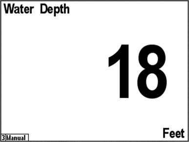
Figure 111 – Numeric Display Example
The upper left hand corner indicates the parameter being display where the center of the screen shows the numeric value for the indicated parameter. The bottom right hand corner shows the units.
6.2 Compass Rose Display
The compass rose display shows a heading, bearing, or course parameter inside a compass rose display. A full-screen example of the heading display can be seen below in Figure 112.
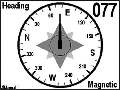
Figure 112 – Compass Rose Display (Course Up) Example
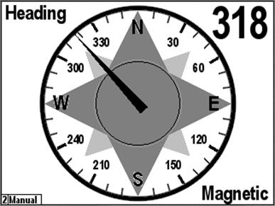
Figure 113 - Compass Rose (North Up) Display
6.3 GPS Status Display
The GPS Status display shows the following data about the selected GPS receiver:
- Satellite signal strength (up to 12 satellites)
- Satellite azimuth and elevation (up to 12 satellites)
- GPS operating mode (2D, 3D, DGPS)
- Position
- HDOP
- Accuracy of position
- Time
- Date
An example of a full-screen GPS Status display can be seen below in Figure 114.
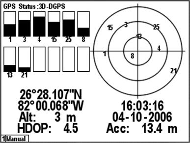
Figure 114 – GPS Status Display Example
6.4 Gauge Display
The gauge display shows the selected data in a graphical format resembling an analog gauge. There is a general gauge format for most types of display, and a specialized rudder gauge display. A full-screen example of the current depth display can be seen in Figure 115 below.
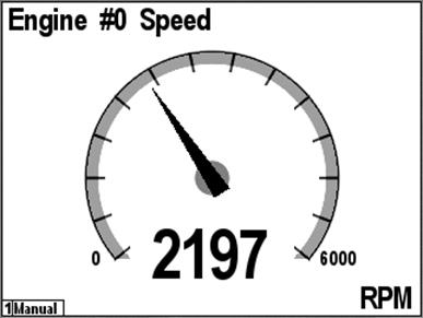
Figure 115 – Gauge Display Example
A full-screen example of the rudder gauge display can be seen in Figure 116 below.
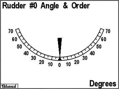
Figure 116 – Rudder Angle Gauge Display Example
6.5 Rolling Road
The DSM200 supports a “Rolling Road”, or navigation highway display. This display repeats transmitted navigation data from a primary navigator, such as a chart plotter or a personal computer running navigation software. Figure 117 below shows the favorites screen setup menu with the rolling road selected. When the rolling road is selected the displayed navigation data, the “Type:” submenu changes to four “Item:” submenus. The rolling road display can show numerical displays of four navigation-related data items in addition to the graphical display of boat position and progress towards the desired waypoint.
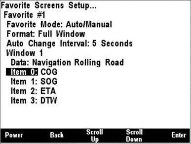
Figure 117 – Configuration of Rolling Road Display
The following data items may be displayed on the rolling road display:
- COG (Course Over Ground)
- SOG (Speed Over Ground)
- ETA (Estimated Time of Arrival)
- TTG (Time to Go)
- DTW (Distance to Waypoint)
- BOD (Bearing, Origin to Destination)
- Set
- Drift
- DTW (Distance to Waypoint)
- VMG (Velocity Made Good)
- BTW (Bearing to Waypoint)
- XTE (Cross Track Error)
Figure 118 below shows a rolling road display. The navigation parameters that have been selected are COG, SOG, ETA, and TTG. On the navigation highway itself, the waypoint name, if available, is displayed on the upper left and the waypoint number, if available, is displayed on the upper right. The dashed vertical line along the center of the highway represents the current leg of the route. The distance of the boat to the left or the right of the line represents the XTE (Cross Track Error). The angle of the boat relative to the vertical line represents the difference between the boat’s COG (Course Over Ground) and the BTW (Bearing to Waypoint). The scale of the XTE display can be selected by setting a value for the XTE alarm (See Section 5.2.1, “Alarms Menu”, on page 16 for details).
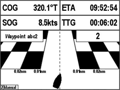
Figure 118 – Rolling Road Display
6.6 Line Graph
The line graph display shows the value of a parameter displayed on the horizontal axis versus time on the vertical axis. Figure 119 below shows the line graph display for barometric pressure over a time period of one day. The line graph display can show the selected data over a time period of 1, 2, 3, 4, 5, 6, or 7 days. Line graph displays are supported only for barometric pressure.
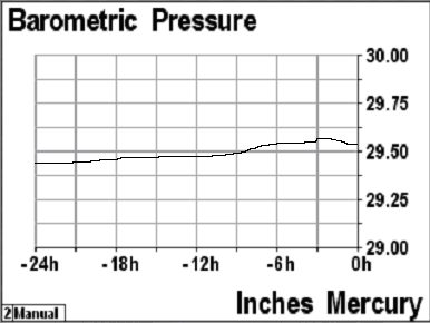
Figure 119 - Line Graph Display
6.7 Weather Display
The DSM200 supports a single-screen weather display that shows a wide variety of weather-related information. A screen shot of the weather display appears in Figure 120 below.
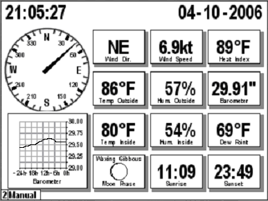
Figure 120 - Weather Display
The weather display shows the following information
- True Wind Direction (Ground Referenced)
- True Wind Speed (Ground Referenced)
- Heat Index / Wind Chill
- Outside Temperature
- Outside Humidity
- Barometric Pressure
- Inside Temperature
- Inside Humidity
- Dew Point
- Moon Phase
- Sunrise
- Sunset
6.8 Wind Rose
The DSM200 supports a wind rose display, which displays apparent wind direction and speed measured relative to the moving vessel, or true wind direction and speed measured relative to the moving vessel, depending on the parameter selected. A screen shot of a wind rose appears in Figure 121 below.

Figure 121 - Wind Rose Display
6.9 Moon Phase Display
The DSM200 supports a moon phase display which shows the current phase of the moon at the current location. An example screenshot of the moon phase display appears in Figure 122 below.

Figure 122 - Moon Phase Display
6.10 Trim Tab Display
The DSM200 supports a trim tab display in which the relative positions of the port and starboard trim tabs are displayed on a dual bar graph. A screenshot of the trim tab display appears in Figure 123 below.
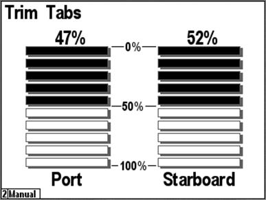
Figure 123 - Trim Tab Display
6.11 Swing Meter Display
The DSM200 supports a swing meter display, similar to those found on dedicated swing meters, for displaying the rate of turn of the vessel in degrees per minute. The swing meter is available in ranges of +/- 30°/minute, +/- 100°/minute, or +/- 300°/minute. A screenshot of the swing meter display appears in Figure 124 below.
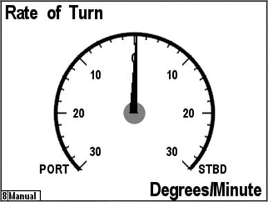
Figure 124 - Swing Meter Display
6.12 Tank Gauge Display
The DSM200 supports a tank level gauge display type which shows percentage of fluid remaining in a tank on an analog gauge with 180° of travel. A screenshot of a tank gauge display showing a fuel tank’s level appears in Figure 125 below.
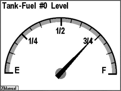
Figure 125 - Tank Gauge Display
7 Maintenance
Regular maintenance is important to ensure continued proper operation of the Maretron DSM200. Perform the following tasks periodically:
- Clean the unit with a soft cloth. Do not use chemical cleaners as they may remove paint or markings or may corrode the DSM200 enclosure or seals.
- Ensure that the unit is mounted securely and cannot be moved relative to the mounting surface. If the unit is loose, tighten the mounting screws.
- Check the security of the cable connected to the NMEA 2000® interface and tighten if necessary.
8 Troubleshooting
If you notice unexpected operation of the Maretron DSM200, follow the troubleshooting procedures in this section to remedy simple problems.
|
Symptom |
Troubleshooting Procedure |
|
No activity on the display |
Check the connection to the NMEA 2000® and connector and tighten if necessary
Ensure that power is supplied to the connected NMEA 2000® cable |
|
Expected data appears as a dash “-“ instead of a value |
Check the device selection menu and ensure that the “Display” parameter is set to “On” for the device that is sending the data (See Section 5.2.2.1.1, “Fuel Management Considerations”, on page 19 for details). Ensure, using a Maretron N2KMeter or similar diagnostic tool, that the device in question is actually transmitting data. Ensure that NMEA 2000 network connections are sound and that two terminators are present on the network. If the data is in the fuel management category, ensure that all fuel tanks and engines whose data is enabled in the Configuration->Data Enable/Disable menu are present and transmitting data (see Section 5.2.2.1.1, “Fuel Management Considerations”, on page 19 for details. |
|
Data fluctuates between two different values |
Check the device selection and ensure that only one device of a given type has its “Display” parameter set to “On” (See Section 5.2.2.1.1, “Fuel Management Considerations”, on page 19 for details). |
If these steps do not solve your problem, please contact Maretron Technical Support (refer to Section 10 for contact information).
Warning: There are no user-serviceable components inside the Maretron DSM200. Opening the DSM200 will expose the sensitive electronic components to adverse environmental conditions that may render the unit inoperative. Please do not open the DSM200, as this will automatically void the warranty. If service is required, please return the unit to an authorized Maretron service location.
9 Technical Specifications
Specifications
|
Parameter |
Value |
Comment |
|
NMEA 2000® Standard |
Level A |
Highest Level of Certification |
|
NMEA 2000® Connector |
DeviceNet Micro-C |
Industry Standard Waterproof |
|
Display Technology |
FSTN Transreflective LCD |
Sunlight Readable |
|
Display Resolution |
320 x 240 Pixels |
QVGA Resolution |
|
Display Viewable Area |
122mm W x92 mm H |
5.7” Diagonal |
|
Display Backlighting |
Red LED |
3 User-Programmed Levels 0-100% |
|
Keyboard |
5 Silicone Rubber Keys |
Red LED Backlighting |
|
Languages Supported |
English, Dutch (Nederlands) |
User Selectable |
Certifications
|
Parameter |
Comment |
|
NMEA 2000® |
Level A |
|
Maritime Navigation and Radiocommunication Equipment & Systems |
Tested to IEC 60945 |
|
FCC and CE Mark |
Electromagnetic Compatibility |
Supported Display Data Types
|
Description |
Data Types |
|
Battery Monitor |
Voltage, Current, Temperature |
|
Compass |
Vessel Heading, Attitude, Rate of Turn |
|
Depth |
Water Depth, Transducer Offset |
|
Engine Monitor |
Oil & Coolant Pres & Temp, Alt, Fuel Rate, Hours, Fuel Pres, Tilt, RPM, Boost Pres |
|
Fuel Management |
Total Fuel Rate, Total Fuel Remaining, Fuel Economy |
|
GPS |
COG, SOG, DOP, Position, Satellites, Time |
|
Primary Navigation |
BTW, DTW, ETA, TTG, XTE, Datum, Set & Drift, Waypoint Number & Name, VMG, BOD, Set, Drift |
|
Rudder Indicator |
Rudder Position |
|
Speed |
Total Log, Trip Log, Speed Through Water |
|
Tank Monitor |
Fluid Level, Tank Capacity, Amount Remaining |
|
Time |
Local & UTC Time & Date, Sunrise, Sunset, Twilight AM, Twilight PM, Moon Phase |
|
Transmission |
Gear, Oil Temperature and Pressure |
|
Vessel |
Pitch, Roll, Trim |
|
Weather Station |
Water Temp, Air Temp, Atmospheric Pres., Sea Temp, Relative Humidity |
|
Wind |
Apparent & True Wind Direction and Speed |
NMEA 2000® Parameter Group Numbers (PGNs)
|
Description |
PGN # |
PGN Name |
Default Rate |
|
Response to Requested PGNs |
126464 |
PGN List (Transmit and Receive) |
N/A |
|
126996 |
Product Information |
N/A |
|
|
126998 |
Configuration Information |
N/A |
|
|
Protocol PGNs |
059392 |
ISO Acknowledge |
N/A |
|
059904 |
ISO Request |
N/A |
|
|
060416 |
ISO Transport Protocol, Connection Management |
N/A |
|
|
060160 |
ISO Transport Protocol, Data Transfer |
N/A |
|
|
060928 |
ISO Address Claim |
N/A |
|
|
065240 |
ISO Address Command |
N/A |
|
|
126206 |
NMEA |
N/A |
|
|
Received PGNs |
126992 |
System Time |
N/A |
|
127237 |
Heading/Track Control |
N/A |
|
|
127245 |
Rudder |
N/A |
|
|
127250 |
Vessel Heading |
N/A |
|
|
127251 |
Rate of Turn |
N/A |
|
|
127257 |
Attitude |
N/A |
|
|
127488 |
Engine Parameters, Rapid Update |
N/A |
|
|
127489 |
Engine Parameters, Dynamic |
N/A |
|
|
127493 |
Transmission Parameters, Dynamic |
N/A |
|
|
127497 |
Trip Parameters, Engine |
N/A |
|
|
127505 |
Fluid Level |
N/A |
|
|
127508 |
Battery Status |
N/A |
|
|
128259 |
Speed |
N/A |
|
|
128267 |
Water Depth |
N/A |
|
|
128275 |
Distance Log |
N/A |
|
|
129025 |
Position, Rapid Update |
N/A |
|
|
129026 |
COG & SOG, Rapid Update |
N/A |
|
|
129029 |
GNSS Position Data |
N/A |
|
|
129033 |
Time & Date |
N/A |
|
|
129283 |
Cross Track Error |
|
|
|
129284 |
Navigation Data |
|
|
|
129285 |
Navigation – Route/WP Information |
|
|
|
129291 |
Set & Drift, Rapid Update |
|
|
|
129538 |
GNSS Control Status |
|
|
|
129539 |
GNSS DOPs |
N/A |
|
|
129540 |
GNSS Sats In View |
N/A |
|
|
130306 |
Wind Data |
N/A |
|
|
130310 |
Environmental Parameters |
N/A |
|
|
130311 |
Environmental Parameters |
N/A |
|
|
130576 |
Small Craft Status |
|
|
|
130577 |
Direction Data |
|
Electrical
|
Parameter |
Value |
Comment |
|
Operating Voltage |
9 to 16 Volts |
DC Voltage |
|
Power Consumption |
<200mA |
Average Current Drain (backlight off) |
|
|
<350mA |
Average Current Drain (backlight on) |
|
Load Equivalence Number (LEN) |
7 |
NMEA 2000® Spec. (1LEN = 50 mA) |
|
Reverse Battery Protection |
Yes |
Indefinitely |
|
Load Dump Protection |
Yes |
Energy Rated per SAE J1113 |
Mechanical
|
Parameter |
Value |
Comment |
|
Size |
6.8” x 5.75” x 1.25” |
Including Flanges for Mounting |
|
Weight |
24 oz. |
|
|
Mounting |
Surface or Flush Mount |
|
Environmental
|
Parameter |
Value |
|
IEC 60954 Classification |
Exposed |
|
Degree of Protection |
IP67 |
|
Operating Temperature |
-25°C to 55°C |
|
Storage Temperature |
-40°C to 70°C |
|
Relative Humidity |
93%RH @40° per IEC60945-8.2 |
|
Vibration |
2-13.2Hz @ ±1mm, 13.2-100Hz @ 7m/s2 per IEC 60945-8.7 |
|
Rain and Spray |
12.5mm Nozzle @ 100liters/min from 3m for 30min per IEC 60945-8.8 |
|
Solar Radiation |
Ultraviolet B, A, Visible, and Infrared per IEC 60945-8.10 |
|
Corrosion (Salt Mist) |
4 times 7days @ 40°C, 95%RH after 2 hour Salt Spray Per IEC 60945-8.12 |
|
|
|
|
Electromagnetic Immunity |
Conducted, Radiated, Supply, and ESD per IEC 60945-10 |
|
Safety Precautions |
Dangerous Voltage, Electromagnetic Radio Frequency per IEC 60945-12 |
10 Technical Support
If you require technical support for Maretron products, you can reach us in any of the following ways:
Fax: 1-602-861-1777
E-mail: [email protected]
World Wide Web: http://www.maretron.com
Mail: Maretron,
LLP
Attn:
Technical Support
9034 N.
23rd Ave Suite 10
Phoenix,
AZ 85021 USA
11 Installation Template
Please check the dimensions before using the following diagram as a template for drilling the mounting holes because the printing process may have distorted the dimensions.
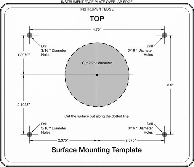
Figure 126 – Surface Mounting Template
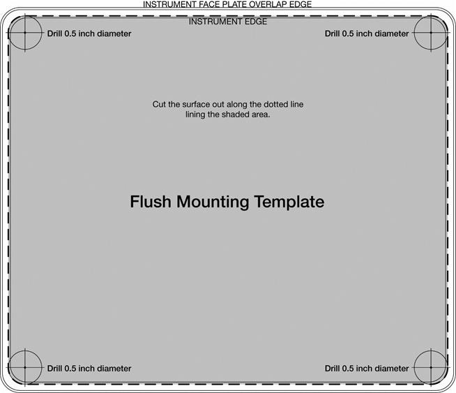
Figure 127 – Flush Mounting Template
12 Maretron (2 Year) Limited Warranty
Maretron warrants the DSM200 to be free from defects in materials and workmanship for two (2) years from the date of original purchase. If within the applicable period any such products shall be proved to Maretron’s satisfaction to fail to meet the above limited warranty, such products shall be repaired or replaced at Maretron’s option. Purchaser's exclusive remedy and Maretron’s sole obligation hereunder, provided product is returned pursuant to the return requirements below, shall be limited to the repair or replacement, at Maretron’s option, of any product not meeting the above limited warranty and which is returned to Maretron; or if Maretron is unable to deliver a replacement that is free from defects in materials or workmanship, Purchaser’s payment for such product will be refunded. Maretron assumes no liability whatsoever for expenses of removing any defective product or part or for installing the repaired product or part or a replacement therefore or for any loss or damage to equipment in connection with which Maretron’s products or parts shall be used. With respect to products not manufactured by Maretron, Maretron’s warranty obligation shall in all respects conform to and be limited to the warranty actually extended to Maretron by its supplier. The foregoing warranties shall not apply with respect to products subjected to negligence, misuse, misapplication, accident, damages by circumstances beyond Maretron’s control, to improper installation, operation, maintenance, or storage, or to other than normal use or service.
THE FOREGOING WARRANTIES ARE EXPRESSLY IN LIEU OF AND EXCLUDES ALL OTHER EXPRESS OR IMPLIED WARRANTIES, INCLUDING BUT NOT LIMITED TO THE IMPLIED WARRANTIES OF MERCHANTABILITY AND OF FITNESS FOR A PARTICULAR PURPOSE.
Statements made by any person, including representatives of Maretron, which are inconsistent or in conflict with the terms of this Limited Warranty, shall not be binding upon Maretron unless reduced to writing and approved by an officer of Maretron.
IN NO CASE WILL MARETRON BE LIABLE FOR INCIDENTAL OR CONSEQUENTIAL DAMAGES, DAMAGES FOR LOSS OF USE, LOSS OF ANTICIPATED PROFITS OR SAVINGS, OR ANY OTHER LOSS INCURRED BECAUSE OF INTERRUPTION OF SERVICE. IN NO EVENT SHALL MARETRON’S AGGREGATE LIABILITY EXCEED THE PURCHASE PRICE OF THE PRODUCT(S) INVOLVED. MARETRON SHALL NOT BE SUBJECT TO ANY OTHER OBLIGATIONS OR LIABILITIES, WHETHER ARISING OUT OF BREACH OF CONTRACT OR WARRANTY, TORT (INCLUDING NEGLIGENCE), OR OTHER THEORIES OF LAW WITH RESPECT TO PRODUCTS SOLD OR SERVICES RENDERED BY MARETRON, OR ANY UNDERTAKINGS, ACTS OR OMISSIONS RELATING THERETO.
Maretron does not warrant that the functions contained in any software programs or products will meet purchaser’s requirements or that the operation of the software programs or products will be uninterrupted or error free. Purchaser assumes responsibility for the selection of the software programs or products to achieve the intended results, and for the installation, use and results obtained from said programs or products. No specifications, samples, descriptions, or illustrations provided Maretron to Purchaser, whether directly, in trade literature, brochures or other documentation shall be construed as warranties of any kind, and any failure to conform with such specifications, samples, descriptions, or illustrations shall not constitute any breach of Maretron’s limited warranty.
Warranty Return Procedure:
To apply for warranty claims, contact Maretron or one of its dealers to describe the problem and determine the appropriate course of action. If a return is necessary, place the product in its original packaging together with proof of purchase and send to an Authorized Maretron Service Location. You are responsible for all shipping and insurance charges. Maretron will return the replaced or repaired product with all shipping and handling prepaid except for requests requiring expedited shipping (i.e. overnight shipments). Failure to follow this warranty return procedure could result in the product’s warranty becoming null and void.
Maretron reserves the right to modify or replace, at its sole discretion, without prior notification, the warranty listed above. To obtain a copy of the then current warranty policy, please go to the following web page: