This document outlines how to configure the CLMD16 using Maretron’s N2KAnalyzer® V3 software
in conjunction with either a Maretron USB100 or a Maretron IPG100 connected to
an active NMEA2000® network. For information on how to use Maretron’s N2KAnalyzer® V3 software or to download the latest
version of Maretron’s N2KAnalyzer® V3 software please
visit:
https://www.maretron.com/products/N2KAnalyzer.php
For N2KAnalyzer® V3 software to configure a CLMD16 unit the
CLMD16 unit must be powered and connected to an active NMEA2000® network.
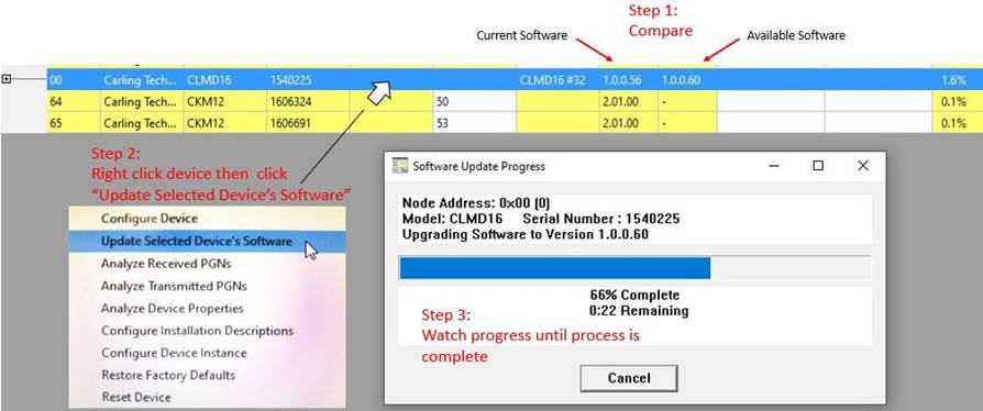
Before attempting to configure CLMD16, always ensure that
you are using the latest version of Maretron N2KAnalyzer® V3 and install the latest software / firmware to your
CLMD16 unit using N2KAnalyzer® V3. To update software for CLMD16 first compare
“Current Software” vs “Available Software”, right click CLMD16 inside
N2KAnalyzer® and click on “Update Selected Device’s Software”. A Dialog Box
will appear showing the software update progress.
·
Successful configuration of a CLMD16 unit consist of configuring
the unit’s various input channels and the unit’s output channels known as ECBs
(Electronic Circuit Breaker)
CLMD16’s Input Channels
could be any of the following:
1) Physical hardwired
inputs to the CLMD16’s input channels on the “J3” connector
(Referred to as
“Binary Events”)
2) NMEA 2000®
Binary Status Report PGN 127501 states
(Referred to as
“Discrete I/O Input”)
3) NMEA 2000® 127500 Load Controller PGN messages which could come
from a third party MFD (Multi-function Display) or any equipment running
Maretron’s N2KView® software. The name of the channels used to receive these
PGN messages are referred to as “Network Inputs 1-16” (One “Network Input”
corresponding with each ECB)
·
Next, “Switching Elements” placed in-between CLMD16’s input
channels and CLMD16’s ECB (Electronic Circuit Breaker) output
channels are “mapped”. CLMD16 Switching Application
Elements (referred to in the guide as “Switching Elements”) consists of any
of the following:
1) “Counter”
2) “Flash”
3) “Latch”
4) “Logic”
5) “Timer”
6) “Toggle”
7) “Toggle
Mode” & “Manual Mode”
·
Lastly, connecting or “mapping” the output of these “Switching
Elements” to the CLMD16’s ECB (Electronic Circuit Breaker) input signals
complete the configuration for each circuit. Note that “Switching Elements” can
be “mapped” to each other, for example the output of a “Toggle Element” can be
an input of a “Logic Element” and that “Logic Element” output can be the input
of a “Timer Element” giving the user ultimate flexibility to configure the
CLMD16. See the “Switching Elements Definition” segment of this guide to learn
the features of each.
·
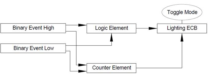
Some circuit configurations require the use of a mode called
“Manual Mode”. By default, when “Manual Mode” is not enabled the CLMD16’s ECBs
can be controlled by compatible third party MFDs. Also, when “Manual Mode” is
not enabled, the ECB control method from a compatible MFD may be limited to the
MFDs internal Switching Application software. Activate “Manual Mode” on any ECB
to sever this direct control allowing for the “Network Input” signal received
from the MFD to be directed into any CLMD16 “Switching Element(s)” then back
into the ECB control input. This feature gives the user the ability to take
advantage of the CLMD16’s “Switching Elements” even using a third party MFD or
multiple MFDs as the main point(s) of control.
In the following depictions you will see visual reference to
what “Toggle” and “Momentary Inputs” mean to the Switching Application. It is
important to understand that “Inputs” do not have to be a person pressing a
switch but could be a signal becoming present. This is also not to be confused
with physical switch types being sustained contact or momentary contact. This
definition is as it applies to the CLMD16 Switching Definition.
Momentary: As long as an Input is present the
Switching Application has an Input.

Toggle: Every
time an Input becomes present or “Turns On” the Switching Application changes
state.

There
is a list of input signals available to be used to activate the various
“Switching Elements” these “Input Signals” consist of the following:
|
Signal Name
|
Description
|
|
None Selected
|
This connects the
specified input to a constant Logic ‘0’ value
|
|
Binary Event 1 through 12 Low
|
The signal on binary event 1
through 12 is in the Low voltage range
|
|
Binary Event 1 through 12
Float
|
The signal on binary event 1
through 12 is in the Float voltage range
|
|
Binary Event 1 through 12
High
|
The signal on binary event
for the numbered channel is in the High voltage range
|
|
Network Input 1 through 16
|
The state of the signal on
Network Input for the numbered channel
|
|
Logic Output 1 through 48
|
The state of the output of
Logic Element for the numbered channel
|
|
Latch Output 1 through 16
|
The state of the output of
Latch Element for the numbered channel
|
|
Toggle Output 1 through 16
|
The state of the output of
Toggle Element for the numbered channel
|
|
Timer Output 1 through 16
|
The state of the output of
Delay Timer Element for the numbered channel
|
|
Flash Output 1 through 16
|
The state of the output of
Flash Element for the numbered channel
|
|
Counter Active 1 through 16
|
The state of the output of
Counter Element 1 through 16
|
|
Over Current Fault Ch 1
through 16
|
An Over Current Fault has
been detected on Channel 1 through 16
|
|
Ch 1 through 16 Tripped
|
The circuit breaker for the
numbered channel is tripped
|
|
Ch 1 through 16 Thermal Limit
Hit
|
The circuit breaker for the
numbered channel has reached its thermal limit
|
|
Discrete I/O 1 through 32
|
The discrete state I/O of the
signal the numbered channel
|
|
Breaker On 1 through 16
|
The state of an Output
Channel for the numbered channel
|
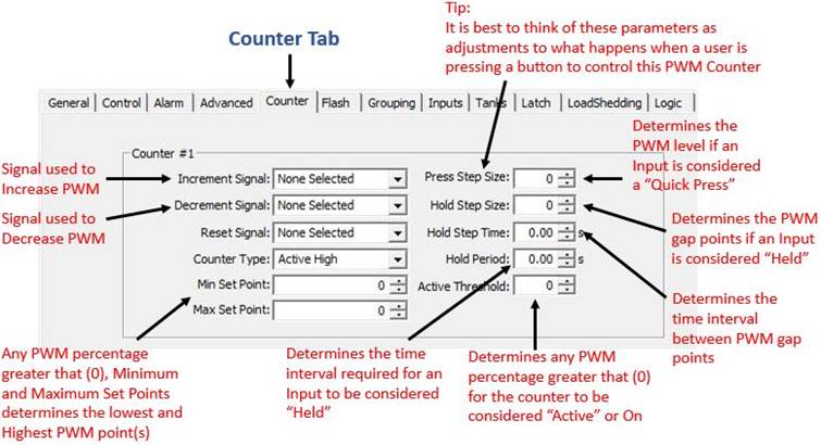
This function is used to adjust incremental and decremental
step points and gap sizes, Min. and Max set points, and user input signal delay
parameters for CLMD16 output channels set to drive PWM (Pulse-Width Modulation).
See following “Counter” dialog for a description of
the basic “Counter” features.
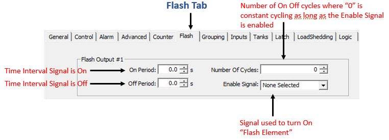
“Flash Element”
This function is used to turn On and Off signals at a user
configurable frequency. See following “Flash” dialog for a description of the
basic “Flash” features.
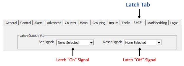
This function, unlike a “Toggle” signal where a single input can turn something
both
On and Off is exactly as it sounds, it “Latches” signals into an On state in
where it requires another signal to “Unlatch” or turn Off. See following “Latch”
dialog for a look at configuration input required for this feature.
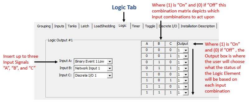
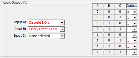
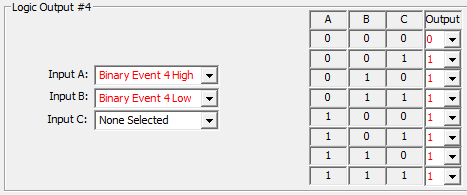
If an ECB breaker requires combinatory Logic rules applied to it a “Logic
Element” must be used. Applying “Logic Elements” will help you to achieve many
desirable results with countless potential solutions. This function is used to
combine up to three different input signals to create a single output using
Boolean Logic method where the user can choose the Logic Output state of On or
Off for any combination of 3 input signals. See
following “Logic” dialog for details on how to set-up a Logic Element.
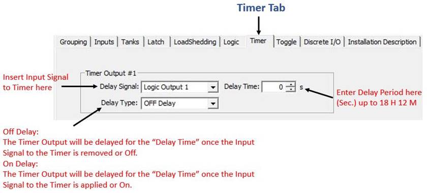
The “Timer” element is used to delay functions for any set time up to 18 hours
and 12 minutes per timer. See following “Timer” dialog for details on how to
set-up a Timer Element.
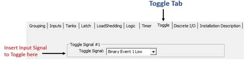
The “Toggle” element is a “Latch” element that does not require two separate
Inputs to change state but instead can turn its Output both On and Off using a
single input. The “Toggle” element will turn its output
On when it detects an Input Signal and when it detects it’s next Input Signal
it will turn its Output Off. See following dialog to familiarize the
“Toggle” set-up.
“Toggle Mode” is
part of the Switching Application that is not an independent “Switching Element”
but instead, a “Switching Element” added to the ECB directly. When this mode is
enabled, the state of the ECB will change to the opposite state whether On or
Off each time an Input Signal changes from Off to On, including ECB direct, “Network
Input” Toggle commands. This command could come from a Digital Switching
compatible MFD or any equipment running Maretron’s N2KView® software.
“Manual Mode” Manual
Mode is part of the Switching Application that is not an independent “Switching
Element” but instead, disallows the ability for devices using NMEA 2000® 127500
Load Controller PGN to have direct ECB control accessibility. This does not
mean the device using 127500 PGN will have no way to gain access to control an
ECB, but instead limits the accessibility to only “Network Inputs 1-16” from
the Available Signals to be used as inputs within the Switching Application.
This feature can be used to funnel commands from any device using 127500 PGN
into CLMD16 Switching Application Logic. By default, “Manual Mode” is not
enabled and the CLMD16’s ECBs can be controlled by compatible third party MFDs
and Maretron’s N2KView® software. Please note, the ECB control method from a
compatible MFD will be limited to the MFD’s internal Switching Application software.
The software used by third-party MFDs is usually limited to Toggle Operation
whereas Maretron’s N2KView® may be able to perform the desired action without
the use of “Manual Mode”. By activating “Manual Mode” on any ECB, direct ECB
control is not possible however, the “Network Input” signal received from the
MFD may be directed into any CLMD16 “Switching Element(s)” then back into the
ECB control input allowing for ultimate configurability such as sequencing,
special lighting control, modes, and group switching even with a third-party
MFD. “Manual Mode” can also be used to disallow access to ECBs that are
designated for Load Sequencing or Sub-Routines.
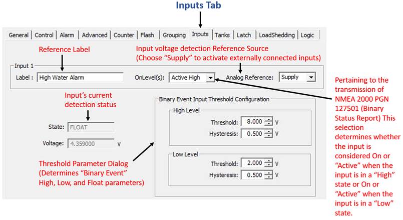
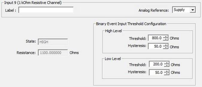
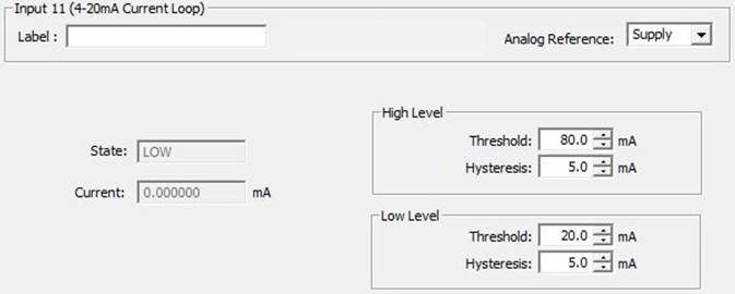
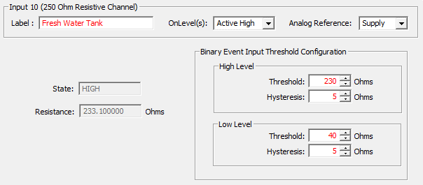
The CLMD16 has 11 hardwired input
channels. Eight of these channels monitor potential connections to supply DC
voltage, two monitor resistance to DC (-) and one is a current loop channel
that will measure 4-20 mA DC (-) current. Each Input has “High Level” and “Low
Level” thresholds as well as “Hysteresis” levels that are user adjustable to
determine what input statuses are. For example, a user can adjust these
thresholds such that a “High Level” threshold is 8v and “Low Level” threshold
is 2v. These settings will translate to; when a DC (+) input of 8v or greater
is detected the input channel is considered within the “High Level” category, when
a DC (+) input of 2v or lower or a DC (-) signal pulling the input channel
“Low” (0v) is detected the input channel is considered within the “Low Level”
category. Anything in-between the “High Level” and “Low Level” categories is
considered inside the “Float” category. The “Hysteresis”, in other words, can
be considered a buffer on both ends of the threshold setting. Hysteresis is
used to “dampen” the threshold mark disallowing the potential of nuisance or
rapid status switching. For example, using the
abovementioned “High Level” threshold of 8v, if an input voltage of “just
about” or “just below” 8v is detected where the input is fluctuating between
under 8v and over 8v the input status will change at the frequency of the
fluctuation. Hysteresis is designed to create a buffer on both ends of the
threshold setting to prevent the potential of rapid status changes. For example,
again using the abovementioned “High Level” threshold of 8v, when a hysteresis
of 0.5v is applied to this threshold value the input status does not change
until 7.5v or under and 8.5v or over. Application of hysteresis creates an
environment where status changes to the input are more affirmative.
Once Input types are entered into the Inputs Dialog, the
“High Level”, “Float” and “Low Level” detection of each input parameter can be plugged
directly into the control input of an ECB or used as inputs to “Switching Elements”
of:
1) “Counter”
2) “Flash”
3) “Latch”
4) “Logic”
5) “Timer”
6) “Toggle”
The names of these input detections are called “Binary Event
Low”,” Binary Event High”, and “Binary Event Float” numbers 1 – 11, (a number
correlating to each Input number) where each number has “Low”, “Float” and
“High” detection giving a total of 33 potential signals for the CLMD16 to act
upon related to these 11 inputs and their threshold states being met.
See
below the three different CLMD16 Dialogs used for
configuring these input types
(Voltage, Resistive, and Current Loop).
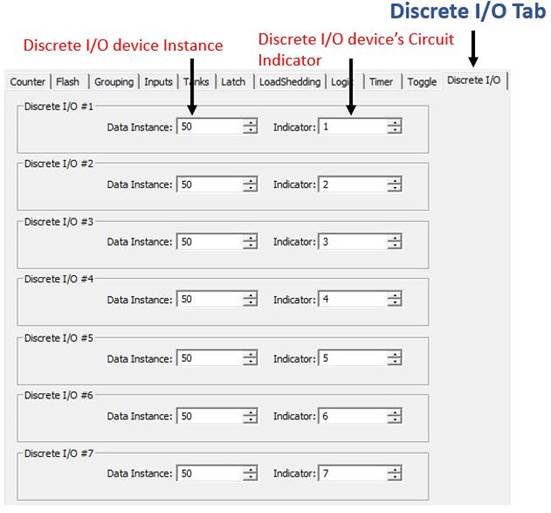
The CLMD16 supports “Discrete I/O” inputs such as signals
from Maretron’s CKM12 and VMM6 units. Configuring the CLMD16 to act upon
“Discrete I/O” inputs starts first with choosing which “Discrete I/O’s” you
want the CLMD16 to “watch for” or be assigned to act upon. Every “Discrete I/O”
device has a unique “Data Instance” for the device as a whole and “Indicator”
numbers corelating with the “Discrete I/O’s” every switch. Apply the “Discrete
I/O” device’s “Data Instance” and “Indicator” number to the CLMD16’s “Discrete
I/O” input channels to then enable these CLMD16 input channels to be used to
plug directly into an ECB control input or used as inputs to “Switching Elements”
of:
1) “Counter”
2) “Flash”
3) “Latch”
4) “Logic”
5) “Timer”
6) “Toggle”
Please note that if the “Discrete I/O” device is to report
the CLMD16’s ECB status, the “Discrete I/O” device itself needs to have each of
its “Indicators” to be assigned to the CLMD16’s “Data Instance” and particular
ECB it is “watching”. See below the CLMD16’s dialog for “Discrete I/O” input
configuration.
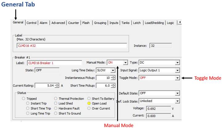
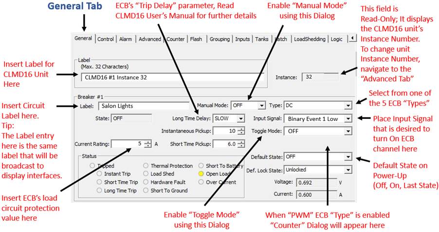
Where the CLMD16’s ECB profiles are configured, the “General
Tab” should be the second if not first configuration point when configuring
CLMD16 then visited again as the last stop to finalize the configuration. This
method is recommended because the “General Tab” is where the ECB circuit names,
and ECB “Type” is configured. By configuring the CLMD16’s ECB or Output
Channels into the configuration first you then know where the final destination
of the Inputs or abovementioned “Switching Elements” will go as Input Signals
to the ECB channel.
There are 5 ECB “Types” to choose from:
1) DC
(Standard On / Off Channel)
2) PWM / PWM W/Counter
(Pulse-Width Modulation Enabled)
3) Soft Start DC
(Standard On / Off Channel with Soft Start Enabled)
4) Full-Bridge
(Reversing Polarity / H-Bridge Enabled)
5) Soft Start Full-Bridge
(Reversing Polarity / H-Bridge with Soft Start Enabled)
See following dialog to acquaint yourself with ECB
configuration.
The CLMD16 is able to broadcast up to three instances of
tank level data via NMEA 2000® 127505 PGN. The following dialog(s) explain the parameters
that will need to be configured for the tank level broadcast.
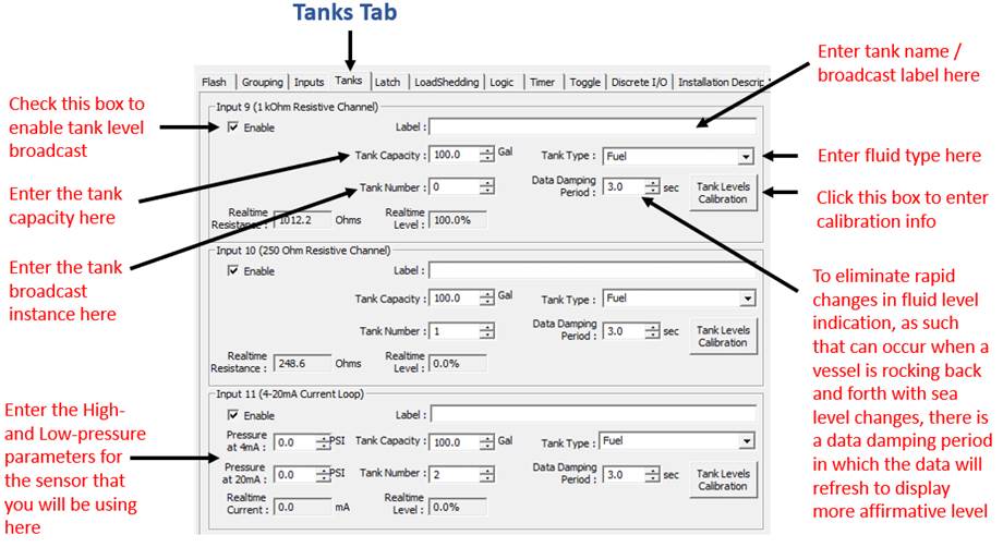
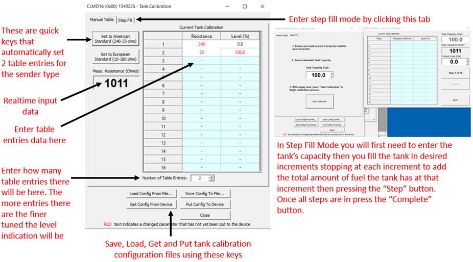
By clicking on “Tank Levels Calibration” another dialog box
will appear. See the following dialog depiction to understand how to enter the
calibration data. Please note the tank level calibrations are not saved with
the CLMD16 device’s overall configuration file but instead, the CLMD16 has the
ability to save each tank level channel’s calibration to individual files. This
is not done automatically when the CLMD16’s configuration is saved as the
configurator will need to save tank calibration data files separately.
Applying a single momentary or sustained contact input
signal to CLMD16 in order for the ECB output to replicate the input signal of
“On” or “Off” is a one-step procedure. See following process to apply inputs to
the CLMD16 ECBs.

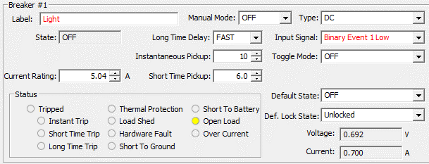
Step 1:
Apply “Input signal” to desired breaker / load output control or
“ECB”. In this example the Input Signal is “Binary Event Low”
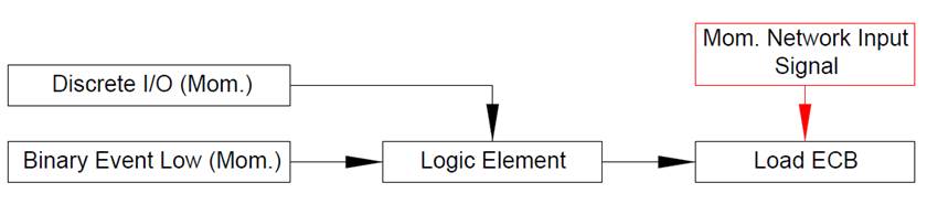
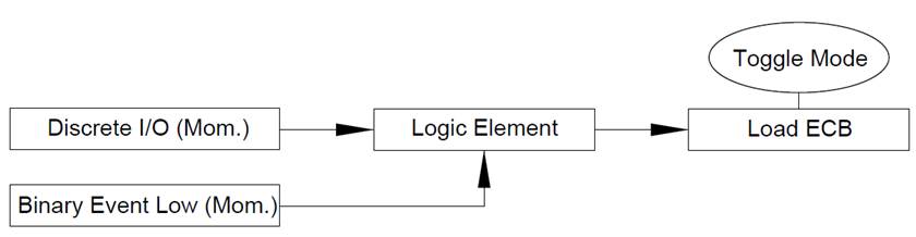
The most efficient configuration for momentary operation of
a CLMD16 ECB load from multiple input sources requires the input sources to be
physically momentary in nature such as a momentary “Discrete I/O” input or an
input from a hardwired switch that has a physical momentary operation. (known
as: “Binary Event”). When adding multiple momentary inputs together to control
an ECB load in a momentary fashion a “Logic Element” will need to be used to
combine the inputs to achieve a single output in which the output of the “Logic
Element” will be applied to the breaker’s “Input Signal”. In the following
example there will be two input signals combined inside a “Logic Element”. One
input is from a hardwired switch that has a momentary DC (-) signal called
“Binary Event Low” and one input is a momentary Discrete I/O input called
“Discrete I/O 1”. Both will switch the desired load in a momentary fashion. See
following steps to configure this circuit type.
Note: a “Momentary Network Input” which could come from a third party MFD using
127500 Load Controller PGN or any equipment running Maretron’s N2KView®
software could be externally applied to control the ECB directly (Shown in
Red).
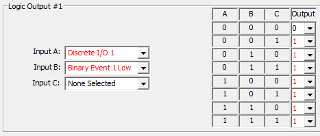
Step 1:
Assign inputs to a “Logic Element”. Where “0” is Off and “1” is On, configure
the “Logic Output” in a manner to where if any input source is On, the “Logic
Element’s Output” becomes active.
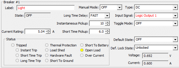
Step 2:
Place “Logic Output” signal into desired ECB control “Input Signal”.
When toggling a circuit On / Off, not all input sources are
treated equally. For example, a “Discrete I/O” input could be a momentary input
requiring a “Toggle Element” added to it. A “Binary Event” (Item hardwired to
an Input to the CLMD16) is subject to be whichever physical switch style the
installer chooses; therefore, the input could be a sustained contact and no
“Toggle Element” will be needed. Multi-Function Displays (MFDs) using 127500 Load Controller PGN or any equipment running
Maretron’s N2KView® software could have direct access to the CLMD16’s ECB
channels and the CLMD16 configuration will not be able to change the Digital
Switching origination command for this type of equipment. Most MFDs Digital
Switching commands are “Toggle style Network Input” by default. For these
reasons, it is vitally important that the configurator understands the
characteristics of each input type used for CLMD16 load switching for proper
configuration.
In the following circuit configuration example, there will be two momentary input sources used to switch a
single CLMD16 load in a toggle fashion. One input is from a hardwired switch that has a momentary DC
(-) signal called “Binary Event Low” and one input is a momentary Discrete I/O
input called “Discrete I/O 1”, both will be used to toggle the single CLMD16
load. The following steps shows how to accurately configure this circuit type.
Step 1:
Assign inputs to a “Logic Element”. Where “0” is Off and “1” is On,
configure the “Logic Output” in a manner to where if any input source is On,
the “Logic Element’s Output” becomes active.
Step 2:
Place “Logic Output” signal into desired ECB control “Input Signal” and
turn on “Toggle Mode”.

Similar to toggling a load On / Off from multiple momentary input
sources, this circuit type adds a “Toggling Network Input” signal into the
circuit. When a CLMD16 ECB is in “Toggle Mode” the ECB will toggle the state
from its current state of “On” or “Off” to the opposite state when the
following occurs: The Rising Edge or “On” detection of an ECB “Toggle Network
Input” or the Rising Edge or “On” detection of a direct ECB “Input Signal”.
This operational mode will allow for a “Toggle Network Input” which could come
from a third party MFD using 127500 Load Controller PGN or any equipment
running Maretron’s N2KView® software plus any applied direct ECB “Input Signal”
to toggle the ECB in harmony with each other. Tip: When an ECB is in “Toggle
Mode” a “Momentary Network Input” signal becomes unaffected by the “Toggle
Mode”.
In the following example, there will be two momentary input
sources and one “Toggle Network Input” signal used to switch a single CLMD16
load in a Toggle fashion. One input is from a hardwired switch that has a
momentary DC (-) signal called “Binary Event Low” and one input is a momentary
Discrete I/O input called “Discrete I/O 1”. There is the additional influence on
the ECB of one externally set (Direct access through 127500 PGN) “Toggle
Network Input” signal. Take note that no different action is required to setup
this circuit type than the “Toggle a Load On / Off
from Multiple Momentary Input Sources” circuit
above. The only difference is the “Toggle Network Input” (shown in red) has
access to the ECB setup by the message’s origination equipment, may it be a third party MFD using 127500 Load Controller PGN or any
equipment running Maretron’s N2KView® software. Because the ECB is in
“Toggle Mode” the ECB’s “Input Signal” and “Toggle Network Input” will work in
harmony with each other toggling the ECB On / Off.
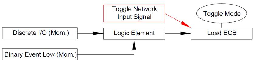
Step 1:
Assign inputs to a “Logic Element”. Where “0” is Off and “1” is On,
configure the “Logic Output” in a manner to where if any input source is On,
the “Logic Element’s Output” becomes active.
Step 2:
Place “Logic Output” signal into desired ECB control “Input Signal” and
turn on “Toggle Mode”.
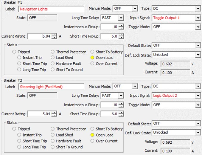
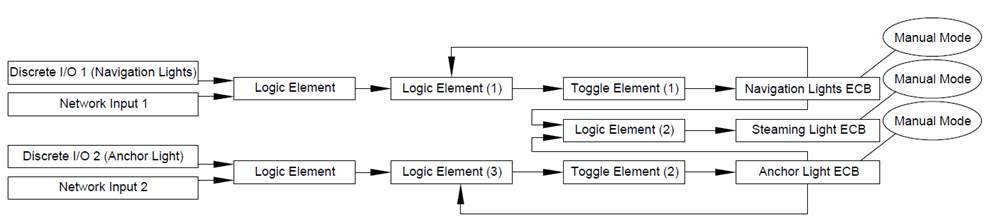
This circuit configuration type operates Navigation lights and
Anchor light loads using two separate “Discrete I/O” (Momentary) inputs. One input
for “Navigation Lights” and one for “Anchor Light”. When “Navigation Lights”
input is commanded both “Navigation Lights” and “Anchor Light” ECBs turn On.
When “Anchor Light” input is commanded “Anchor Light” ECB turns On. When
“Anchor Light” input is commanded while “Navigation Lights” ECB is On, the
“Navigation Lights” ECB is turned Off and “Anchor Light” ECB remains On. In
this example, “Discrete I/O 1” is used for “Navigation Lights” and “Discrete
I/O 2” is used for “Anchor Light”.
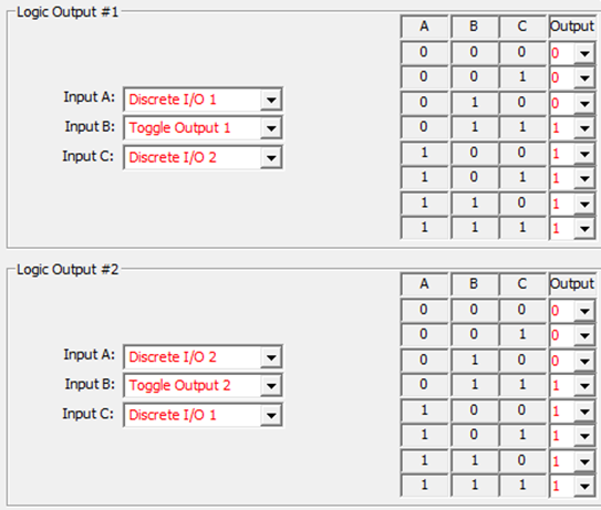
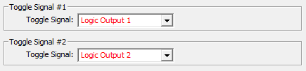
Step 1:
Choose appropriate output rules for the “Logic Elements” that will make
this circuit possible. Where 0 is Off and 1 is On, attention to the logic
output correlation to the input combination must be paid for proper operation. Notice
that the output for the “Logic Element” #1 (Used for Navigation Lights) will
turn On therefor Toggling the ECB in two states, first, with “Discrete I/O 1”
and also with “Discrete I/O 2” if the “Toggle Output 1” is already in the On
state, therefore toggling the ECB Off. The same occurs for “Logic Element #2”
(Used for Anchor Lights). In this manner each opposite input or “Discrete I/O”
cancels the other.
Step 2:
Place “Logic Output” signals into “Toggle Elements”.
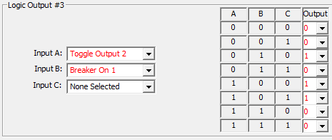
Step 3:
Create an intervening “Logic Element” for the “Anchor Light” circuit. This
“Logic Element” is used to ensure each time the “Navigation Lights” ECB
(Breaker 1) is On the “Anchor Light” ECB (Breaker 2) will turn On as well.
Select the “Logic Output” in where if either “Logic Inputs” turn On so does the
Output.
Step 4:
Place “Toggle Output” signal into “Navigation Lights” ECB and the
intervening “Logic Output” signal into “Anchor Light” breaker inputs. Ensure
“Toggle Mode” is Off.
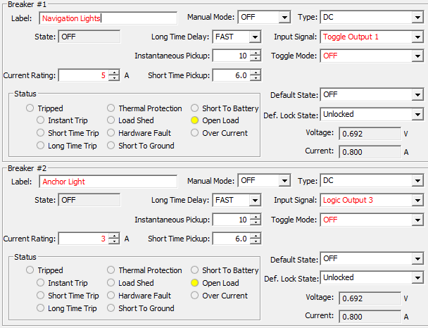
Note:
Because a third party MFD using 127500 Load Controller PGN or any equipment
running Maretron’s N2KView® software, by default, will have direct access to
control the above-mentioned ECBs (#1 & 2) the “Navigation Lights Logic”
circuit shown here will only operate via “Discrete I/O 1 & 2”. The same
“Navigation Lights Logic” behavior may be able to be replicated inside the
internal logic of the equipment having direct control accessibility (N2KView®)
or if this logic needs to be accessed by third party MFD, “Manual Mode” can be
enabled severing this direct control access. Combinatory “Logic Elements” can
be inserted before the “Logic Element 1” and “Logic Element 2” to add “Network
Inputs 1 & 2” to the scheme enabling the same “Navigation Lights Logic”
behavior via “Network Inputs 1 & 2” as long as the signal is a momentary
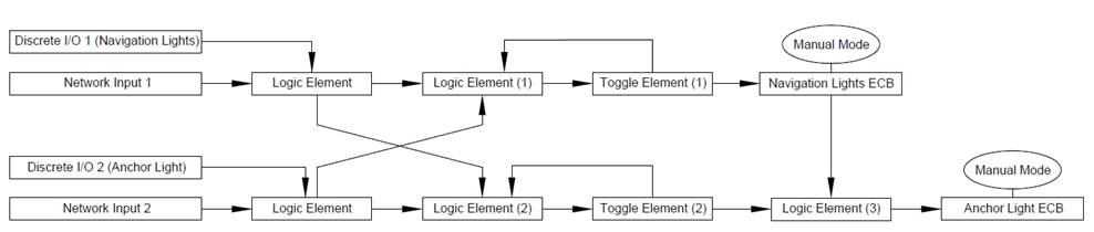
type Input Signal. The mapping for this exact circuit would look as shown below:
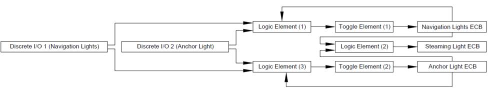
This circuit configuration type operates Navigation lights
and Steaming Light (Fwd Mast) using one “Discrete I/O” input then Steaming
Light (Fwd Mast) and Anchor light (Aft Mast) using a second “Discrete I/O” input.
When “Navigation Lights” “Discrete I/O” input is commanded both “Navigation
Lights” and “Steaming Light” (Fwd Mast) ECBs turn On. When “Anchor Light” “Discrete
I/O” input is commanded “Anchor Light” (Aft Mast) + “Steaming Light” (Fwd Mast)
ECBs turn On. When “Anchor Light” “Discrete I/O” input is commanded while
“Navigation Lights” ECB is On, the “Navigation Lights” ECB Output is turned Off
and “Anchor Light” (Aft Mast) ECB output turns On while “Steaming Light” (Fwd
Mast) ECB stays On.
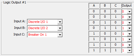
Step 1:
Choose appropriate output rules for the “Logic Elements”:
In this example Discrete I/O 1 is “Navigation Lights” and Discrete I/O 2 is
“Anchor Light”. Where 0 is Off and 1 is On, attention to the logic output
correlation to the input combination must be paid for proper operation. Just as
the previous circuit above (“Navigation / Anchor
Lights Toggle Logic using two Momentary Input Signals”), there will be
rulesets that allow for Logic Output operation to occur only when the status of
a breaker is already On for the “Logic Elements” associated with “Navigation
Lights” ECB and “Anchor Light” (Aft Mast) ECBs. Notice the “Logic Element”
associated with the “Steaming Light” ECB allows for the ECB to turn On when
either ECB 1 (Navigation) or ECB 2 (Anchor) is in the On state.
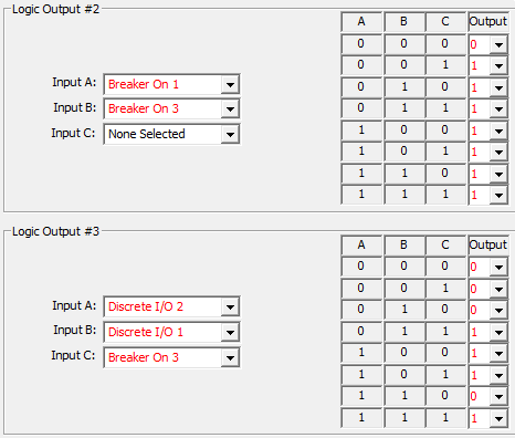
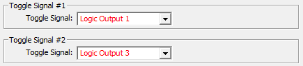
Step 2:
Place “Logic Output” signals 1 and 3 into “Toggle Elements”.
Step 3:
Place “Toggle and Logic Output” signals into ECB “Input Signal” locations.
Ensure “Toggle Mode” is Off.
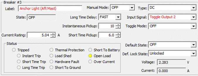
Note:
Because a third party MFD using 127500 Load Controller PGN or any equipment
running Maretron’s N2KView® software, by default, will have direct access to
control the above-mentioned ECBs (#1-3) the “Navigation Lights Logic” circuit
shown here will only operate via “Discrete I/O 1 & 2”. The same “Navigation
Lights Logic” behavior may be able to be replicated inside the internal logic
of the equipment having direct control accessibility (N2KView®) or if this
logic needs to be accessed by third party MFD, “Manual Mode” can be enabled
severing this direct control access. Two combinatory “Logic Elements” can be
inserted before the “Logic Elements 1 & 3” to enable the same “Navigation
Lights Logic” behavior via “Network Inputs 1 & 2” as long as the signal is
a momentary type of Input Signal. The mapping for this exact circuit would look
as shown below:
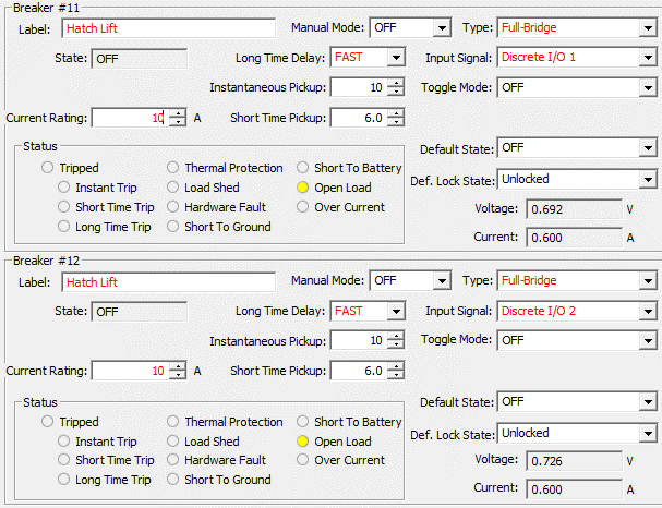
Use this circuit type to control any load requiring
reversing polarity up to 12A. Apply this circuit to a motor or some electric
actuators to reverse directionality. Setting up this circuit type requires a
one step process unless adding multiple control points. To add control points,
apply the control points to a “Logic Element” then plug the “Logic Output” into
the ECBs “Input Signal”. Breakers 1,2 and 11,12 are capable of reverse polarity
drive. The step required to setup this circuit type is to change EBC “Type” to
“Full-Bridge” or “Soft Start Full-Bridge” See following Dialog to see configuration
example.
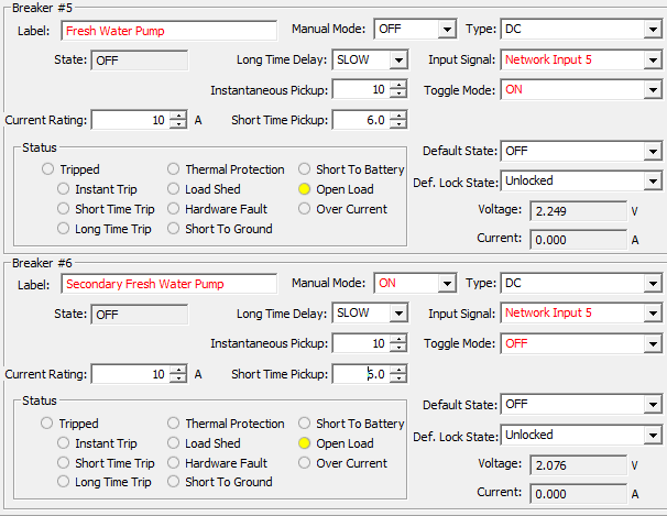
In the following example there is a single freshwater pump
controlled by “Network Input” in a vessel however the end user desires to add
another pump but wishes to continue to use only one switch to control both
pumps. The first pump already has a control circuit. See the following step to
configure the second pump.
Step 1:
Find the original freshwater pump’s control source, in this example it is “Network
Input 5”. Replicate the “Input Signal” of the original pump’s “Input Signal” to
the new secondary pump’s “Input Signal”. The secondary pump is only desired to
be controlled by the original Pump’s ECB control, for this reason, the
secondary pump ECB’s “Manual Mode” will need to be enabled. This dis-allows Breaker
#6’s direct control of the secondary pump by “Network Input 6”, but instead
will allow for only control of Breaker #6 by the “Input Signal” selected
(“Network Input 5”). Turn “Toggle Mode” for Breaker #6 Off to ensure Breaker #6
will follow the state of the original freshwater pump’s control.
This circuit example utilizes a “Flash Element” to operate a
load called “Mast Strobe”. The following steps will outline how to configure this
load to automatically turn On / Off with the frequency of On for 3 Sec. and Off
for 2 Sec. triggered by a momentary input.

Step 1:
Assign Momentary Input to Toggle Element:
In this example “Discrete I/O 8” is the input signal to enable the mast
strobe circuit.

Step 2:
Where “0” is infinite cycles, set-up “Flash Element” details.
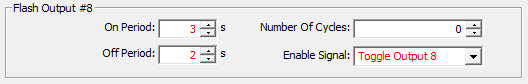
Step 3:
Apply “Flash Output” to Mast Strobe ECB. Ensure Toggle Mode is Off.

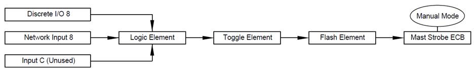
Note:
Because a third party MFD using 127500 Load Controller PGN or any equipment
running Maretron’s N2KView® software, by default, will have direct access to
control ECB #8 (Breaker #8), the “Flash Element” shown here will only operate
via “Discrete I/O 8”. The same “Flash” behavior may be able to be replicated
inside the internal logic of the equipment having direct control accessibility (N2KView®)
or if this logic needs to be accessed by third party MFD, “Manual Mode” can be
enabled severing this direct control access. A combinatory “Logic Element” can
be inserted before the “Toggle Element” to enable the same “Flash” behavior via
“Network Input 8” as long as the signal is a momentary type
of Input Signal. The mapping for this exact circuit would look as shown
below:
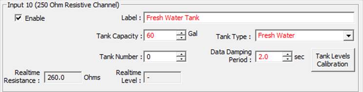
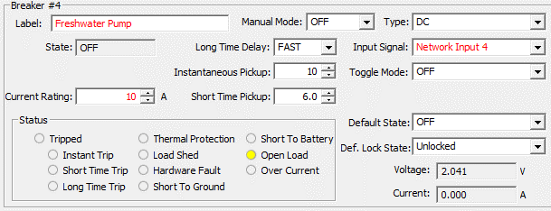
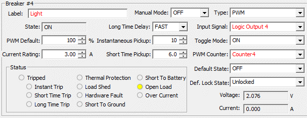
In the following example there will be a freshwater pump
load that turns Off based on tank level becoming low and restores functionality
when filled back up. The freshwater pump in this example is connected to “ECB /
Breaker 4” and the “Freshwater Tank” we are monitoring is connected to “Input
10”. The intent of this is so the freshwater pump does not run dry potentially
damaging the pump. Using this circuit type can prevent unwanted damage to pumps
as well as a way to keep fluid systems primed. See the following example to
setup this circuit type.
Step 1:
Understand what resistance readings equate to “Full” and “Empty” to the CLMD16.
Press “Tank Levels Calibration” on the particular input used for the freshwater
tank sender. Understanding that 240 Ohms = “Tank Empty” / 0%, We will use “230
Ohms” as our “Marker” for when we want the freshwater pump connected to breaker
4 to switch Off. It is recommended that this “Marker” is determined by judging
“Measured Resistance” ohm reading when calibrating for accuracy in determining
the best “Marker Point”.
Step 2:
Remembering our “Marker Point” of: “230 Ohms” the next step will be to navigate
to the “Inputs Tab” and create a “Binary Event High Level” based on this
“Marker Point”. The reason this is going to be a “High Level” indication is
because the variable resistive sender Ohm level continuously goes higher as to
tank level gets lower in fluid level.
Step 3:
Next, an interjection of a “Logic Element” needs to be inserted into the
freshwater pump circuit control. Find out what type of “Input Signal” is
currently being used for the freshwater pump load. In this case it is “Network
Input 4”. Remove “Network Input 4” and add an available “Logic Element”. In
this example we are going to use “Logic Output 4”. Ensure “Toggle Mode” is Off
as “Toggle Mode” changes the state of the breaker every time and “Input Signal”
is detected therefore this will cause the pump not to restore its state when
the tank is re-filled. Also because we do not want to allow for direct ECB control
accessibility, turn “Manual Mode” on.
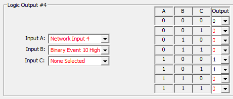
From:
To:
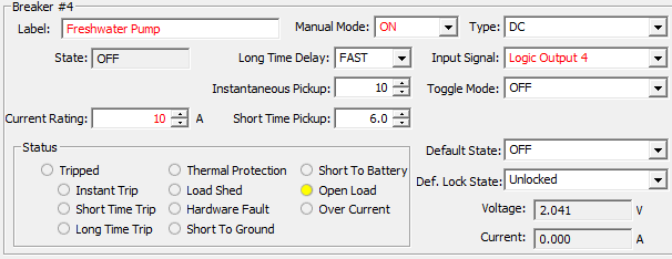
Step 4:
Now, Using the newly created “Binary Event High” signal, add this signal to the
interjected “Logic Element” and place the original freshwater control “Input
Signal” that was “Network Input 4” into the “Logic Element” as well. Select the
logic element’s output parameters such that when the “Binary Event High” signal
is met the “Logic Output” turns off consequently turning off the freshwater
pump.
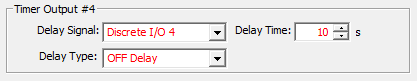
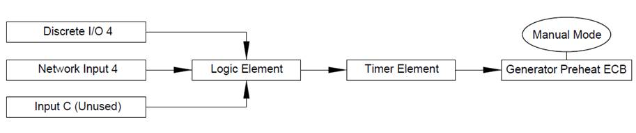
This Circuit uses a “Timer Element”. In this example there
will be a “Delay Off” signal used to “Time” a load named “Generator Preheat”
that needs to be triggered by “Discrete I/O 4” (Momentary Input). The generator
requires a 10s timed signal to preheat the generator. See following steps to
setup a circuit of this type.

Step 1:
Place the Input Signal used to trigger the “Generator Preheat” Circuit into the
“Timer Element” “Delay Signal”. Set up the “Timer Element” parameter for “Off
Delay” and apply the needed 10s. This will make for when the “Delay Signal” is
enabled (after releasing the momentary “Network Input 4” or turning it “OFF”) the
circuit will stay On for 10s.
Step 2:
Apply “Timer Output” into the “Input Signal” of the breaker used for the
Generator Preheat.
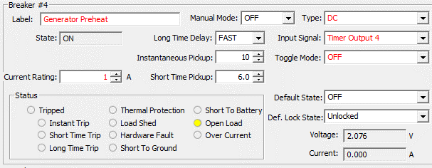
Note:
Because a third party MFD using 127500 Load Controller PGN or any equipment
running Maretron’s N2KView® software, by default, will have direct access to
control ECB #4 (Breaker #4), the “Timer Element” shown here will only operate
via “Discrete I/O 4”. The same “Timer” behavior may be able to be replicated
inside the internal logic of the equipment having direct control accessibility (N2KView®) or if this logic needs to be accessed by third
party MFD, “Manual Mode” can be enabled severing this direct control access.
A combinatory “Logic Element” can be inserted before the “Timer Element” to
enable the same “Timer” behavior via “Network Input 4” as long as the signal is
a momentary type of Input Signal. The mapping for this exact circuit would look
as shown below:
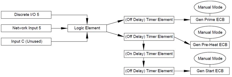
In this example there will be a sequence of 2 timed events
using “Timer Elements” to start the process of Priming, Pre-heating, and
starting a Generator where these items must be handled in a manner of sequence.
First sequence being to “Prime” and “Pre-Heat” and last sequence to “Start”.
The input used to start this sequence is “Discrete I/O 5” (Momentary Input) and
called “Gen Start”. Each “Timer Element” will trigger an ECB / breaker output
for each of the three actions the Generator will need to start (Prime, Preheat,
Start). The generator requires 5s to “Prime”, 10s to “Pre-Heat” and 4s to
“Start”.
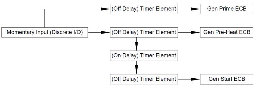
Step 1:
Place desired Momentary Input (Discrete I/O 5) to start the “Timer Elements”
for “Prime” and “Pre-Heat”. Add the output of the Pre-Heat “Timer Output” to
another “Timer Element” where the “Timer Element” has an “On Delay” equivalent
to the time the “Pre-Heat” “Timer Element” is set to (10s). Add the output of
the “On Delay” “Timer Element” to the “Timer Element” that will be used for the
4s “Start” signal.
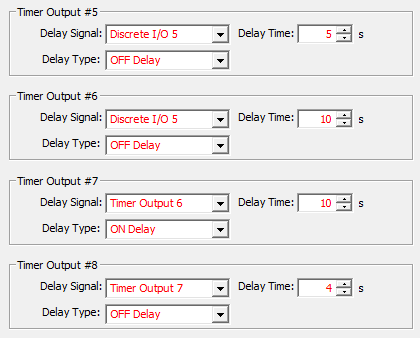
Step 2:
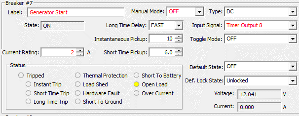
Apply “Timer Outputs” to appropriate Breaker “Input Signals” for each sequence
function
( Prime, Preheat, Start). Ensure “Toggle Mode” is off on each ECB.

Note:
Because a third party MFD using 127500 Load Controller PGN or any equipment
running Maretron’s N2KView® software, by default, will have direct access to
control all three ECBs shown in this example, the “Circuit Sequence” shown in
this example will only operate via “Discrete I/O 5”. The same “Circuit
Sequence” behavior may be able to be replicated inside the internal logic of
the equipment having direct control accessibility (N2KView®) or if this logic
needs to be accessed by third party MFD, “Manual Mode” can be enabled to each
ECB severing this direct control access. A combinatory “Logic Element” can
be the “Input Signal” of each “Timer Element” to enable the same “Circuit
Sequence” behavior via “Network Input 5” as long as the signal is a momentary type
of Input Signal. The mapping for this exact circuit would look as shown below:
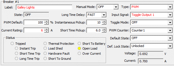
In this example there is a load called “Galley Lights” that
can have one or more momentary inputs to toggle the lights On / Off if the
momentary input is turned On with a “Quick Press”. If the momentary input is
“Held”, the lights will dim up/ dim down (PWM up / down) as long as the input
is On or “Held”. If the input is “Held” and then released at the desired dim
level (PWM level) the dim level is retained for each time the load is toggled
On using a “Quick Press” until the next time the input is “Held”. This feature is
obtained by the use of PWM “Counter” also known as a “Counter Element”. See
following steps to setup this circuit type for one or more control points.
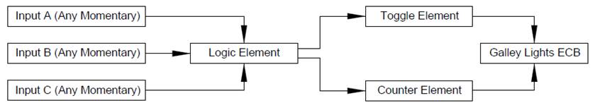
Step 1:
Apply the desired momentary inputs to control this circuit to a “Logic
Element”. Where “0” is Off and “1” is On, configure the
“Logic Output” in a manner to where if any input source is On the “Logic
Element’s Output” becomes active. This step is not necessary if only one
control point is necessary for the circuit. If only one control point is being
used for this circuit place that control input in the stead of “Logic Output
1”.
Step 2:
Apply “Logic Output” to the “Counter Element”, Select “One Button Smooth
Scroll” for the “Counter Type” Set “Counter” parameters. The parameters
depicted in this example are a good choice for this circuit type however can be
adjusted as desired.
Step 3:
Apply “Logic Output” to a “Toggle Element”

Step 4:
After setting the ECB “Type” to “PWM”, Apply both the “Toggle Output” and the
“Counter Element” to the ECB parameters. Ensure “Toggle Mode” is Off.
Note:
The “One Button Smooth Scroll” shown in this example will only operate via
“Discrete I/O 1” and “Binary event 1 Low”. When a “Counter” is selected the
“One Button Smooth Scroll” behavior cannot be replicated by any equipment
having direct control accessibility to the ECB via 127500 Load Controller PGN
including N2KView® but instead the load will only
Toggle On / Off. If this behavior is desired by MFD, the use of “Toggle Mode”
and elimination of the “Toggle Element” show in this example is acceptable. If
this logic needs to be accessed by third party MFD or N2KView®, “Manual Mode”
can be enabled to the ECB and “Network Input” for breaker 1 (Network Input 1)
can be added to “Input C” of “Logic Element 1” therefor allowing “One Button
Smooth Scroll” behavior to occur via “Network Input” such as control from Third
Party MFD or N2KView®. Keep in mind, “One Button
Smooth Scroll” operates via momentary Input only. If dimming a circuit from
N2KView® only is desired, select “None” in the “PWM Counter” Dialog and enable
PWM control from N2KView®.
In this example there is a hardwired input to CLMD16 wired
to “Input 4”. This hardwired input is connected directly to the center position
of the SPDT switch one side of the switch is wired to DC (+) and the other to
DC (-). If the ECB output is off and the switch is
activated one direction and held, the CLMD16 hardwired input will receive DC
(-) and the ECB output will PWM down or dim. If the ECB output is off and the
switch is activated and held the other direction, the hardwired input will
receive DC (+) and the ECB output will PWM up or brighten. When the switch is
activated in either direction in a quick manner, the ECB will toggle On if Off
and Off if On while recalling the last PWM state.
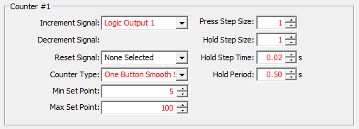
Step 1:
Populate a “Logic Element” that contains both “Binary Event High” (Connected to
DC+) and “Binary Event Low” (Connected to DC-) for the appropriate DC Input (In
this example it is “Input 4”). Where “0” is Off and “1” is On, configure the
“Logic Output” in a manner to where if any input source is On the “Logic
Element’s Output” becomes active.
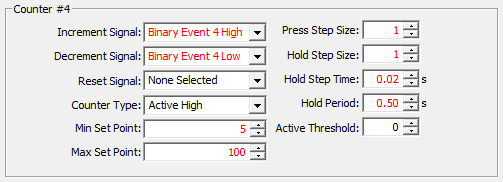
Step 2:
Setup “Counter” where the “Increment Signal” is the “Binary Event High” signal,
and the “Decrement Signal” is “Binary Event Low”. Because it is not desired to
Dim down below 5% set the “Minimum Set Point” to 5. Set the Maximum to 100. See
other parameters for a generic setting used for lighting where the “Hold Period”
(Correlating to the amount of time the input must be held before dimming) is
set to 0.5s and the time in between PWM steps is 0.02s with a PWM “Step Size”
set in 1% PWM gap.
Step 3:
Setup ECB parameters. Ensure “Toggle Mode” is On. Place the “Logic Output” into
the “Input Signal” and be sure to select “PWM” as the ECB “Type” this will
allow for the entry of the “Counter”.
Note:
If this circuit does not operate, please ensure parameter settings defining
“Binary Event Low” and “Binary Event High” are set in accordance with the
defining voltages that the CLMD16 will be receiving from your input source.
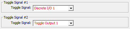
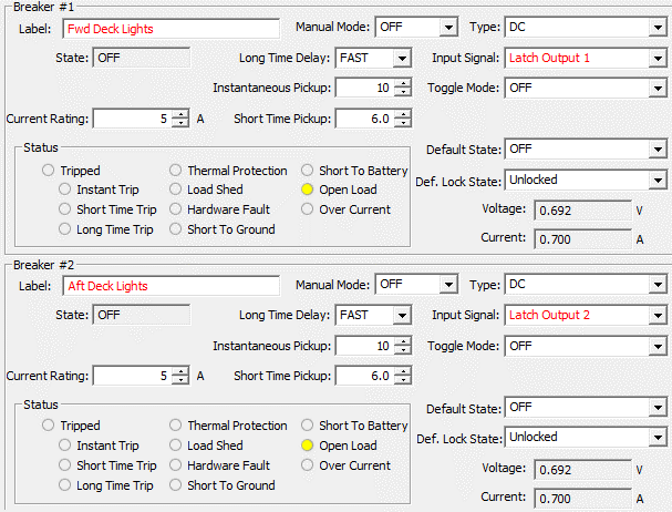
In the following example there is a circuit that has two
loads, one load is called “Fwd. Deck Lights” and one load is called “Aft Deck
Lights”. It is the desire for this circuit to operate from a single input
(Discrete I/O 1) where “Press 1” turns On “Fwd Deck Lights”, “Press 2” turns On
“Aft Deck Lights”, “Press 3” turns On both, “Press 4” turns both Off. See the
following example steps to setup a circuit of this type.
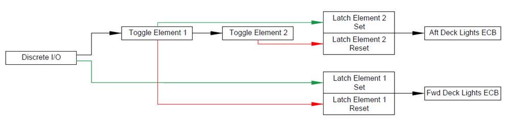
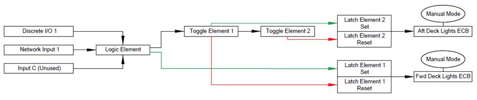
Step 1:
Place circuit control input (Discrete I/O 1) into a “Toggle Element”, then add
the output of the first “Toggle Element” into a second “Toggle Element”
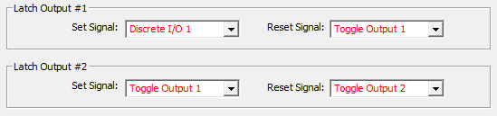
Step 2:
Place the circuit control input into a “Latch Element”, “Set Signal”. The
output of the first “Toggle Element” goes into the “Reset Signal”. Creating
another “Latch Element” place the output of the first “Toggle Element” into the
“Set Signal” field. In the “Reset Signal” field place the output of the second
“Toggle Element”.
Step 3:
Apply the outputs of the “Latch Elements” into the “Input Signal” field of the
two load ECB parameter dialogs. Ensure “Toggle Mode” is Off.
Note:
Because a third party MFD using 127500 Load Controller PGN or any equipment
running Maretron’s N2KView® software, by default, will have direct access to
control ECB #s 1 & 2 Separately (Breakers #1 & 2), the “Toggle
Sequence” shown here will only operate via “Discrete I/O 1”. The same “Toggle
Sequence” behavior may be able to be replicated inside the internal logic of
the equipment having direct control accessibility (N2KView®) or if this logic
needs to be accessed by third party MFD, “Manual Mode” can be enabled to both
ECBs severing this direct control access. A combinatory “Logic Element” can be
inserted before “Toggle Element 1” and “Latch Element 1” to enable the same “Toggle
Sequence” behavior via “Network Input 1” as long as the signal is a momentary type
of Input Signal. The mapping for this exact circuit would look as shown below:
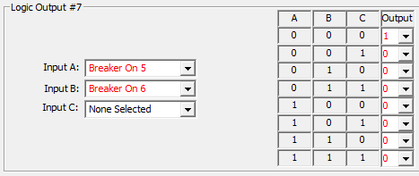
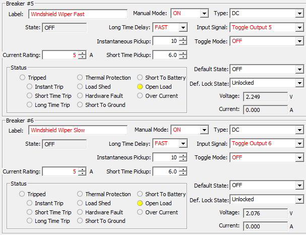
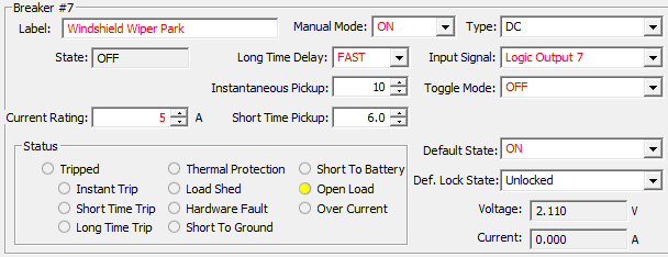
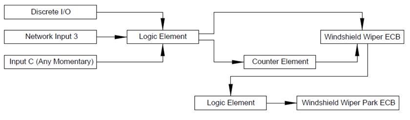
In the following example there is a windshield wiper motor
that accepts a DC (+) output for each speed. One for “Fast” and one for “Slow”.
The windshield wiper system will need a “Park” signal (DC +) that will need to
be applied when the wiper is not in “Slow” or “Fast” operation. The circuit
will take a total of 3 outputs from CLMD16. The “Fast” operation will have to
disable the “Slow” operation and vise-versa as the wiper motor cannot accept
both signals at once. The “Park” signal must be On by default, turn Off when
the “High” or “Low” operations are On and restore to the On state when “Fast”
and “Slow” are Off. The control for this circuit will be “Discrete I/O 5” for
“Fast” and “Discrete I/O 6” for “Slow” See the following example steps to setup
a circuit of this type.
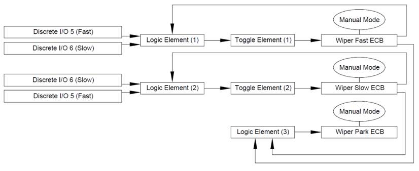
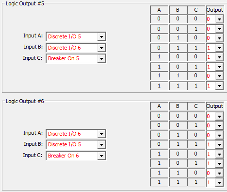
Step 1:
Because this circuit is mostly done within the “Logic Element” Switching Logic,
It is best to start with the “Logic Elements”. In this example, “Logic Elements
5-7” will correspond with ECBs 5-7 respectively. Where “0” is Off and “1” is
On, configure the “Logic Output” in a manner where each “Discrete I/O” used for
control will cancel the other, yet the opposing Discrete I/O will not allow for
the Output to do so unless the ECB is On. Do this by using the “Breaker On”
signal. Notice the arrangement for the “Logic Output 7” where the output will
not turn On unless both ECBs 5 and 6 are Off.
Step 2:
Place the “Logic Outputs” of the “Fast and Slow” speed ECBs into “Toggle
Elements”
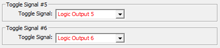
Step 3:
Map the “Toggle Elements” and the single “Logic Element” into the ECBs “Input
Signals”. ensure “Toggle Mode” is Off. Because damage to the motor can occur if
operated incorrectly, it is best this circuit has “Manual Mode” enabled on its
ECBs. This will prevent an MFD using 127500 Load Controller PGN to have direct
access to control the ECBs.
Note:
The same Windshield Wiper Control behavior may be able to be replicated
inside the internal logic of equipment having direct control accessibility
(N2KView®) or any third party MFD using 1275000 Load Controller PGN. If this
logical circuit needs to be accessed by third party MFD, two combinatory “Logic
Elements” can be inserted into the circuit allowing “Network Input” control of
this circuit as long as the signal is a momentary type of Input Signal. The
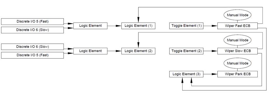
mapping for this exact circuit would look as shown below:
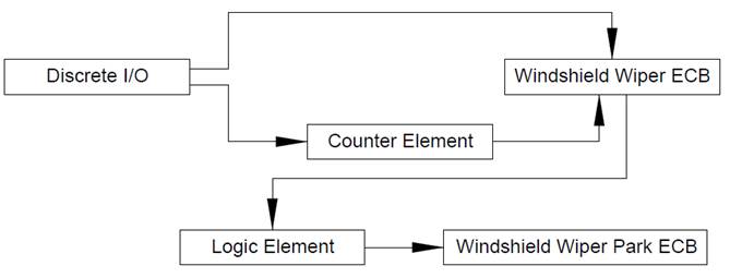
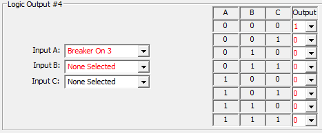
In the following example there is a windshield wiper motor
that is PWM compatible for speed control. The customer wants to have one
Discrete I/O key that will turn the wiper motor On and Off and use the same key
to adjust the speed at start-up. One ECB output will be used as a PWM type ECB
to make this speed control happen however there is the need for a second ECB to
be used to enable the “Park” signal for the wiper motor. The “Park” signal
needs to be On whenever the wiper motor power / speed control ECB is Off. The
following example shows how this circuit type will be arranged using “Discrete
I/O 3” as the circuit control.
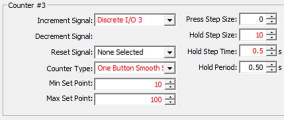
Step 1:
Place desired parameters into the “Counter Element” that will be used for the
speed control. This example will use “One Button Smooth Scroll” as the “Counter
Type” allowing for a loop of steps in PWM from PWM “Min Set Point” to “Max set
point” then back down to “Min set point” in a continuous loop. The PWM counter
does not start until the “Hold Step Time” is reached. The “Hold Step Size” is
10% therefore giving the wiper motor a total of 9 speeds between 10% PWM and
100% PWM.
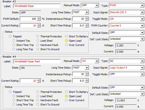
Step 2:
Arrange the ECB parameters. For the ECB used as the speed control output to the
motor, set the ECB to “PWM” type with the appropriate “Counter Element”
assigned to the ECB. Ensure “Toggle Mode” is On for this ECB. Set the ECB
parameters for the windshield wiper “Park” signal choosing an available “Logic
Element” as the “Input Signal”. Ensure “Toggle Mode” is Off for this ECB.
Because the ECB used for the “Park” signal should not be influenced by any
outside signals turn “Manual Mode” on for this ECB.
Step 3:
Add the “Park” signal Logic. Where “0” is Off and “1” is On, configure the “Logic
Output” in a manner where the “Logic Output” will always be On when the ECB
used for the speed control is Off.
Note:
Because of the use of a “Counter Element” the same Windshield Wiper Control
behavior will not be able to be replicated inside the internal logic of any equipment
having direct control accessibility to the ECBs including N2KView® or any third
party MFD using 1275000 Load Controller PGN. If this logical circuit needs to be
accessed by third party MFD, a single combinatory “Logic Element” can be
inserted into the circuit allowing “Network Input” control of this circuit as
long as the signal is a momentary type of Input Signal. The mapping for this
exact circuit would look as shown below:
For
further information about Maretron’s MPower Digital Switching solutions, please
visit,
https://www.maretron.com/