1 General
1.1 Introduction
Congratulations on your purchase of the Maretron Current Loop Monitor (CLM100). Maretron has designed and built your monitor to the highest standards for years of reliable, dependable, and accurate service.
Maretron’s CLM100 converts commercially available 4-20mA transducers into digital data so a wide variety of information can be displayed on compatible NMEA 2000® displays. Numerous 4-20mA transducers are supported by the CLM100 including transducers for monitoring DC voltage and current, flow rate, distance, linear velocity and acceleration, angle, angular velocity and acceleration, temperature, humidity, resistance, strain gauges, force (load cell), pressure, decibels, and rotational rate. Some typical applications where the CLM100 is used together with a commercial available 4-20mA transducer include machinery monitoring using accelerometers and vibration sensors. Vibration monitoring of pumps, motors, fans, compressors, and gear boxes provides an early warning of potential problems resulting fewer breakdowns and reduced maintenance expenses. Another application example using the CLM100 is shaft speed monitoring. A commercially available 4-20mA rotational rate sensors is coupled to the shaft of interest and the CLM100 converts the transducer to an RPM that can be read on by a compatible NMEA 2000® display. And if you’re concerned about the force exerted on a mast stay or perhaps a vessel tow attachment point, commercially available clevis pins with 4-20mA interface can be connected to the CLM100 and the corresponding load monitored using any of Maretron’s display products.
The Maretron CLM100 is designed to operate within the harsh demands of the marine environment. However, no piece of marine electronic equipment can function properly unless installed, calibrated, and maintained in the correct manner. Please read carefully and follow these instructions for installation, calibration, and usage of the Maretron CLM100 in order to ensure optimal performance.
1.2 Firmware Revision
This manual corresponds to CLM100 firmware revision 1.0.0.
1.3 Features
The Maretron CLM100 has the following features:
- NMEA 2000® interface
- Adapts up to six 4-20mA transducers to the NMEA 2000 network
- Each channel independently programmable to transmit the following parameters:
- DC Voltage
- DC Current
- Flow Rate
- Distance
- Linear Velocity
- Linear Acceleration
- Angle
- Angular Velocity
- Angular Acceleration
- Temperature
- Humidity
- Resistance
- Strain Gauge
- Force (Load Cell)
- Pressure
- Decibels
- Rotational Rate – can be used to monitor shaft speed or engine RPM
1.4 CLM100 Accessories
Maretron offers the following pressure transducer accessories for the CLM100:
· PT-V-0-1BAR-01 Pressure Transducer Vacuum to 1 Bar (14.5 PSI)
· PT-0-3PSI-01 Pressure Transducer 0 to 3 PSI (0.21 bar)
· PT-0-5PSI-01 Pressure Transducer 0 to 5 PSI (0.34 bar)
· PT-0-10PSI-01 Pressure Transducer 0 to 10 PSI (0.69 bar)
· PT-0-50PSI-01 Pressure Transducer 0 to 50 PSI (3.45 bar)
· PT-0-100PSI-01 Pressure Transducer 0 to 100 PSI (6.89 bar)
· PT-0-300PSI-01 Pressure Transducer 0 to 300 PSI (20.68 bar)
· PT-0-500PSI-01 Pressure Transducer 0 to 500 PSI (34.47 bar)
· PT-0-1000PSI-01 Pressure Transducer 0 to 1000 PSI (68.95 bar)
· PT-0-3000PSI-01 Pressure Transducer 0 to 3000 PSI (206.84 bar)
· PT-0-5000PSI-01 Pressure Transducer 0 to 5000 PSI (344.74 bar)
· PT-SNUB-01 Pressure Snubber
|
|
WARNING
Maretron pressure transducers are not approved for use with gasoline. If you wish to use the CLM100 to monitor pressures of gasoline, you must obtain a pressure transducer that is approved for use with gasoline. |

For other parameters, Maretron does not offer any accessories for the CLM100; however, the CLM100 is compatible with any transducer which offers an industry standard 4-20mA current loop interface and is able to operate with a current loop excitation voltage of 12-15VDC.
1.5 Quick Install
Installing the Maretron CLM100 involves the following steps. Please refer to the individual sections for additional details.
1. Unpack the Box (Section 3.1)
2. Choose a Mounting Location (Section 3.2)
3. Mount the CLM100 (Section 3.3)
4. Connect the CLM100 (Section 3.4)
5. Configure or Program Each Channel (Section 4.1)
1.6 Theory of Operation
The CLM100 operates by measuring the current transmitted by 4-20mA current loop transducers. The current reading is translated to a parameter value according to the channel’s operating mode as well as the 4mA and 20mA parameter calibration values.
The CLM100 can be used with either 2-wire or 4-wire 4-20mA current loop transducers.
Standard NMEA 2000 messages are used for parameters wherever possible. Proprietary messages are used for other parameters.
|
Parameter |
PGN |
|
DC Voltage |
127751 DC Voltage/Current |
|
DC Current |
127751 DC Voltage/Current |
|
Flow Rate |
65286 Fluid Flow Rate (Maretron Proprietary) |
|
Distance |
130840 Generic Sensor (Maretron Proprietary) |
|
Linear Velocity |
130840 Generic Sensor (Maretron Proprietary) |
|
Linear Acceleration |
130840 Generic Sensor (Maretron Proprietary) |
|
Angle |
130840 Generic Sensor (Maretron Proprietary) |
|
Angular Velocity |
130840 Generic Sensor (Maretron Proprietary) |
|
Angular Acceleration |
130840 Generic Sensor (Maretron Proprietary) |
|
Temperature |
130316 Temperature, Extended Range |
|
Humidity |
130313 Humidity |
|
Resistance |
130840 Generic Sensor (Maretron Proprietary) |
|
Strain Gauge |
130840 Generic Sensor (Maretron Proprietary) |
|
Force (Load Cell) |
130840 Generic Sensor (Maretron Proprietary) |
|
Pressure |
130314 Actual Pressure |
|
Decibels |
130840 Generic Sensor (Maretron Proprietary) |
|
Rotational Rate |
130840 Generic Sensor (Maretron Proprietary) |
1.7 Resolution
The CLM100 can measure parameters with a resolution of approximately 0.33% of full scale.
In many cases, the resolution to which the CLM100 can measure a parameter may be lower than the resolution at which NMEA 2000 represents the parameter. As an example, if a channel of the CLM100 is connected to a humidity sensor whose 4mA value corresponds to 0% relative humidity, and whose 20mA value corresponds to 100% relative humidity, the CLM100 can measure and transmit humidity at a resolution of 0.33% relative humidity. However, NMEA 2000 can represent humidity at a resolution of 0.004%. In this case, the capabilities of the CLM100 is what limits the resolution of the parameter values that will be transmitted over the network to 0.33%.
Depending on the type of data being monitored, resolution might further be limited by the resolution of the underlying NMEA 2000 data types used to transmit the parameter value. For example, if you connected a DC voltage sensor with a range of 0-20VDC to the CLM100, the CLM100 could measure the parameter transmitted by the CLM100 to a resolution of 0.067V; however, NMEA 2000 can only represent voltage to a resolution of 0.1V, so in this case, the NMEA 2000 data representation is what limits the resolution of the parameter values that will be transmitted over the NMEA 2000 network to 0.1V.
Finally, the resolution to which the CLM100 can measure a parameter may be limited by the current loop transducer. If the current loop transducer’s resolution is lower than that of the NMEA 2000 representation and the CLM100’s current measurement capability, then the resolution of the current loop transducer will limit the resolution of the value that will be transmitted over the NMEA 2000 network.
Please refer to the configuration section (Section 4) for information on units and NMEA 2000 range and resolution for the different data types supported by the CLM100.
1.8 Accuracy
The CLM100’s accuracy is specified at 1% of the full scale. From the previous example, that means that the humidity value transmitted by the CLM100 will be within 1% of the humidity value transmitted by the humidity sensor over its 4-20mA current loop interface. When considering the accuracy of the measurement on the NMEA 2000 network, the accuracy specification of the sensor itself needs to be considered along with the CLM100’s accuracy specification.
2 Parameters
The following table describes the categories where you can find the parameters to create components to display them or set alarms based on them in Maretron display products:
|
Parameter |
Menu Location |
|
DC Voltage |
DCàVoltage |
|
DC Current |
DCàCurrent |
|
Flow Rate |
Fluid FlowàFlow Rate |
|
Distance |
MotionàDistance |
|
Linear Velocity |
MotionàVelocity |
|
Linear Acceleration |
MotionàAcceleration |
|
Angle |
MotionàAngle |
|
Angular Velocity |
MotionàAngular Velocity |
|
Angular Acceleration |
MotionàAngular Acceleration |
|
Temperature |
Environmentà(Bait Well, Engine Room, etc.) Temperature Temperatureà(Bait Well, Battery, etc.) Temperature |
|
Humidity |
Environmentà(Inside, Outside, etc.) Humidity Humidityà(Inside, Outside, etc.) Humidity |
|
Resistance |
ElectricalàResistance |
|
Strain Gauge |
MechanicalàStrain |
|
Force (Load Cell) |
MechanicalàForce |
|
Pressure |
EnvironmentàBarometric Pressure Pressure/Vacuumà (Barometric, Compress Air, etc.) Pressure |
|
Decibels |
MechanicalàdB |
|
Rotational Rate |
MotionàRotational Rate |
3 Installation
3.1 Unpacking the Box
When unpacking the box containing the Maretron CLM100, you should find the following items:
· 1 – CLM100 Current Loop Monitor
· 1 – Parts Bag containing 4 Stainless Steel Mounting Screws
· 1 – CLM100 User’s Manual
· 1 – Warranty Registration Card
If any of these items are missing or damaged, please contact Maretron.
3.2 Choosing a Mounting Location
Please consider the following when choosing a mounting location.
- The CLM100 is waterproof, so it can be mounted in a damp or dry location.
- The orientation is not important, so the CLM100 can be mounted on a horizontal deck, vertical bulkhead, or upside down if desired.
- The CLM100 is temperature-rated to 55°C (130°F), so it should be mounted away from engines or engine rooms where the operating temperature exceeds the specified limit.
3.3 Mounting the CLM100
Attach the CLM100 securely to the vessel using the included stainless steel mounting screws or other fasteners as shown in Figure 1Figure 1 below. Do not use threadlocking compounds containing methacrylate ester, such as Loctite Red (271), as they will cause stress cracking of the plastic enclosure.
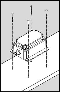
Figure 1 – Mounting the CLM100
3.4 Mounting the Transducer
Please refer to the instructions supplied with the transducer for mounting the transducer.
3.5 Connecting the CLM100
The CLM100 requires two types of electrical connections: 1) the NMEA 2000® connection (refer to Section 3.5.1), and 2) the 4-20mA current loop transducer connections, which are described in Section 3.5.2.
3.5.1 NMEA 2000® Connection
The NMEA 2000® connector can be found on the side of the enclosure. The NMEA 2000® connector is a round five pin male connector (see Figure 2Figure 2). You connect the CLM100 to an NMEA 2000® network using a Maretron NMEA 2000® cable (or an NMEA 2000® compatible cable) by connecting the female end of the cable to the CLM100 (note the key on the male connector and keyway on the female connector). Be sure the cable is connected securely and that the collar on the cable connector is tightened firmly. Connect the other end of the cable (male) to the NMEA 2000® network in the same manner. The CLM100 is designed such that you can plug or unplug it from an NMEA 2000® network while the power to the network is connected or disconnected. Please follow recommended practices for installing NMEA 2000® network products.
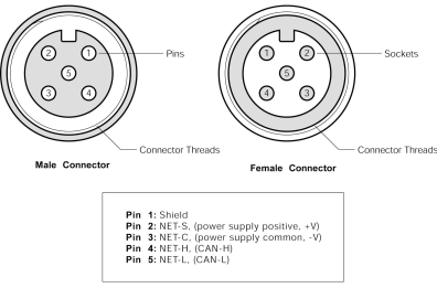
Figure 2 – NMEA 2000® Connector Face Views
3.5.2 Transducer Connections
The CLM100 transducer connections are made by connecting to the 12-pin terminal strip on the top of the unit. First, remove the four screws at the corners of the unit detaching the splash guard from the unit. On the bottom of the splash guard, you will find a label detailing the wire connection to pin number assignments, which are repeated in the table below.
|
Pin # |
Signal Name |
Connection |
|
|
1 |
P0+ |
Transducer 0 |
(positive terminal) |
|
2 |
P0- |
(negative terminal) |
|
|
3 |
P1+ |
Transducer 1 |
(positive terminal) |
|
4 |
P1- |
(negative terminal) |
|
|
5 |
P2+ |
Transducer 2 |
(positive terminal) |
|
6 |
P2- |
(negative terminal) |
|
|
7 |
P3+ |
Transducer 3 |
(positive terminal) |
|
8 |
P3- |
(negative terminal) |
|
|
9 |
P4+ |
Transducer 4 |
(positive terminal) |
|
10 |
P4- |
(negative terminal) |
|
|
11 |
P5+ |
Transducer 5 |
(positive terminal) |
|
12 |
P5- |
(negative terminal) |
|
Please refer to Figure 3 for connecting the CLM100 to a 4-20mA current loop transducer. This figure shows the connection of the 4-20mA transducer to channel 0 via the terminals named P0+ and P0-. Connections to other channels are similar.
|
|
WARNING
The CLM100 supplies loop power each the 4-20mA current loop transducer. Do not connect the current loop wires from the transducer to anything except for the terminals on the CLM100. Do not connect any external power supply or gauge to the transducer wires that form the current loop. |

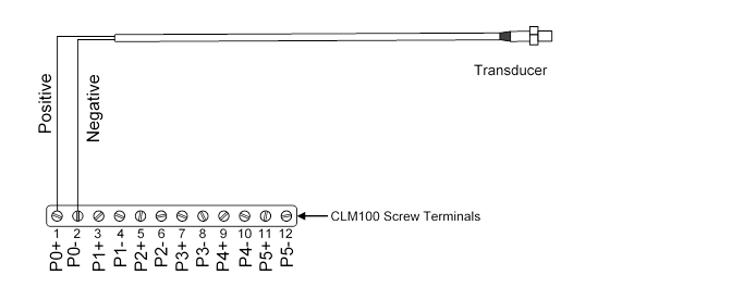
Figure 3 – 4-20mA Transducer Connection Diagram
3.5.3 Extension of Transducer Wires
|
|
WARNING
The transducer cable may be extended. However, you must ensure that when the transducer is connected to the CLM100 with the extended cable, the excitation voltage measured at the transducer meets the minimum excitation voltage specification of the transducer when the transducer is sourcing 20mA. |
The CLM100 supplies a minimum of 12V to each transducer at the maximum loop current of 20mA. In order to ensure that your transducer will work with extended wires, you should calculate the voltage drop across the extension wires. The amount of voltage drop can be calculated as follows:
Look up the resistance per unit length of the wire you are
using (![]() )
from the following table. Be sure to use the value which matches your length
measurement units:
)
from the following table. Be sure to use the value which matches your length
measurement units:
|
Wire Gauge (AWG) |
|
|
|
26 |
40.81 |
133.9 |
|
24 |
25.67 |
84.22 |
|
22 |
16.14 |
52.96 |
|
20 |
10.15 |
33.31 |
|
18 |
6.385 |
20.95 |
|
16 |
4.016 |
13.17 |
|
14 |
2.525 |
8.286 |
|
12 |
1.588 |
5.211 |
|
10 |
0.998 |
3.277 |
Calculate the voltage drop across the cable by multiplying the maximum current (20mA) times the length of the cable. For example, if you are extending the cable by 500 ft. and are using 22AWG wire, then the voltage drop is calculated as follows:
First, calculate the resistance of the wire RWIRE. Remember that the wire length LWIRE needs to be multiplied by two, because the current needs to travel from the CLM100 to the transducer and then back again.
![]()
Now, multiply the resistance of the wire by the maximum
current (20mA) to calculate the total voltage drop across the extension cable ![]() .
.
![]()
Finally, subtract the voltage drop from the minimum power
supply voltage created by the CLM100 to calculate the voltage at the transducer
![]() .
.
![]()
So, for this example, if your transducer can operate with a minimum supply voltage of 11.68V, the wire can be extended to this length.
If your calculated ![]() is
less than the minimum supply voltage specification of your transducer, then you
have two choices:
is
less than the minimum supply voltage specification of your transducer, then you
have two choices:
· Move the CLM100 closer to the transducer to reduce the wire length, or
· Use a larger gauge wire to reduce the wire resistance
4 Configuring the CLM100
The CLM100 has several configurable parameters, which are shown below including the default values. If you are not using the default values, then you will need to refer to the corresponding section for configuring the CLM100 appropriately.
The CLM100 can be configured using Maretron’s DSM150 or DSM250 display, or with Maretron’s freely-available N2KAnalyzer software running on a Windows PC interfacing to the NMEA 2000 network through a Maretron USB100 or IPG100 gateway. Please refer to the appropriate configuration tool’s user’s manual for details on how to configure the CLM100 with that product.
4.1 Configuring Channel Mode
The CLM100 has 6 individually configurable channels. Each channel can be programmed to operate in one of the following modes:
· DC Voltage
· DC Current
· Flow Rate
· Distance
· Linear Velocity
· Linear Acceleration
· Angle
· Angular Velocity
· Angular Acceleration
· Temperature
· Humidity
· Resistance
· Strain Gauge
· Force (Load Cell)
· Pressure
· Decibels
· Rotational Rate (Shaft Speed, RPM)
· Disable – The channel is disabled and transmits no data over the NMEA 2000 network
The Disable mode requires no configuration. The following sections describe in detail the configuration of a CLM100 channel for the other operating modes.
4.2 Configuring a Channel in DC Voltage Mode
The following sections describe the parameters that are available for configuration for a channel which has been set to DC Voltage mode.
4.2.1 Configuring Instance
Program this parameter to match the desired instance of the DC voltage reading for this channel. You can program this parameter to any value between 0 and 252.
|
|
NOTE
If one channel is configured to DC Voltage mode, a second channel is connected to DC Current mode, and the instance numbers for the two channels are the same, then the corresponding DC voltage measurement and DC current measurement will be transmitted together in a single message. |

4.2.2 Configuring Label
Program this parameter with a text string which identifies the particular parameter being monitored by this channel. Maretron display products will display this label text when you are selecting data to display.
4.2.3 Units, Range, and Resolution
Maretron products support the following units for display of DC voltage, with the range and resolution shown in the following table (NOTE: the resolution may be further limited by the capabilities of the CLM100; please refer to section 1.7 for details).
|
Unit |
Minimum Value |
Maximum Value |
Resolution |
|
Volts |
0 |
6553.2 |
0.1 |
4.2.4 Configuring DC Voltage at 4mA
Program this parameter to match the reading of the DC voltage transducer when it is sourcing a current of 4mA. You can determine this value by examining the specification of the DC voltage transducer being used.
4.2.5 Configuring DC Voltage at 20mA
Program this parameter to match the reading of the DC voltage transducer when it is sourcing a current of 20mA. You can determine this value by examining the specification of the DC voltage transducer being used.
4.2.6 Configuring Data Damping Period
You can configure a damping parameter to smooth the DC voltage readings or make them more responsive. The data damping is configurable between 0.2-25.0 seconds with a resolution of 0.1 seconds. The default data damping for a channel in DC voltage mode is 0.2 seconds.
4.3 Configuring a Channel in DC Current Mode
The following sections describe the parameters that are available for configuration for a channel which has been set to DC Current mode.
4.3.1 Configuring Instance
Program this parameter to match the desired instance of the DC current reading for this channel. You can program this parameter to any value between 0 and 252.
|
|
NOTE
If one channel is configured to DC Voltage mode, a second channel is connected to DC Current mode, and the instance numbers for the two channels are the same, then the corresponding DC voltage measurement and DC current measurement will be transmitted together in a single message. |

4.3.2 Configuring Label
Program this parameter with a text string which identifies the particular parameter being monitored by this channel. Maretron display products will display this label text when you are selecting data to display.
4.3.3 Units, Range, and Resolution
Maretron display products and software support the following units for display of DC current, with the range and resolution shown in the following table (NOTE: the resolution may be further limited by the capabilities of the CLM100; please refer to section 1.7 for details).
|
Unit |
Minimum Value |
Maximum Value |
Resolution |
|
Amperes |
-83886.08 |
83886.05 |
0.01 |
4.3.4 Configuring DC Current at 4mA
Program this parameter to match the reading of the DC current transducer when it is sourcing a current of 4mA. You can determine this value by examining the specification of the DC current transducer being used.
4.3.5 Configuring DC Current at 20mA
Program this parameter to match the reading of the DC current transducer when it is sourcing a current of 20mA. You can determine this value by examining the specification of the DC current transducer being used.
4.3.6 Configuring Data Damping Period
You can configure a damping parameter to smooth the DC current readings or make them more responsive. The data damping is configurable between 0.2-25.0 seconds with a resolution of 0.1 seconds. The default data damping for a channel in DC current mode is 0.2 seconds.
4.4 Configuring a Channel in Flow Rate Mode
The following sections describe the parameters that are available for configuration for a channel which has been set to flow rate mode.
4.4.1 Configuring Source
You can configure a “Source” descriptor to be transmitted with the flow rate reading which is used to provide an indication of the source of the flow rate data for this channel. Choices are as follows:
· Fuel
· Fresh Water
· Waste Water
· Live Well
· Oil
· Black Water (Sewage)
4.4.2 Configuring Instance Number
Program this parameter to match the desired instance number of the flow rate reading for this channel. You can program this parameter to any value between 0 and 252.
4.4.3 Units, Range, and Resolution
Maretron display products and software support the following units for display of flow rate, with the range and resolution shown in the following table (NOTE: the resolution may be further limited by the capabilities of the CLM100; please refer to section 1.7 for details).
|
Unit |
Minimum Value |
Maximum Value |
Resolution |
|
Gal(Imp)/h |
-184,523.56 |
184,523.49 |
0.022 |
|
Liter/h |
-838,860.7 |
838,860.4 |
0.1 |
|
Gal(US)/h |
-221,603.55 |
221,603.47 |
0.026 |
|
Gal(Imp)min |
-3,075.3927 |
3,075.3915 |
0.00037 |
|
Liter/min |
-13891.01 |
13891.01 |
0.0017 |
|
Gal(US)/min |
-3693.39 |
3693.39 |
0.00043 |
4.4.4 Configuring Label
Program this parameter with a text string which identifies the particular parameter being monitored by this channel. Maretron display products will display this label text when you are selecting data to display.
4.4.5 Configuring Flow Rate at 4mA
Program this parameter to match the reading of the flow rate transducer when it is sourcing a current of 4mA. You can determine this value by examining the specification of the flow rate transducer being used.
4.4.6 Configuring Flow Rate at 20mA
Program this parameter to match the reading of the flow rate transducer when it is sourcing a current of 20mA. You can determine this value by examining the specification of the flow rate transducer being used.
4.4.7 Configuring Data Damping Period
You can configure a damping parameter to smooth the flow rate readings or make them more responsive. The data damping is configurable between 0.2-25.0 seconds with a resolution of 0.1 seconds. The default data damping for a channel in flow rate mode is 0.2 seconds.
4.5 Configuring a Channel in Distance Mode
The following sections describe the parameters that are available for configuration for a channel which has been set to distance mode.
4.5.1 Configuring Instance Number
Program this parameter to match the desired instance number of the distance reading for this channel. You can program this parameter to any value between 0 and 252.
4.5.2 Configuring Label
Program this parameter with a text string which identifies the particular parameter being monitored by this channel. Maretron display products will display this label text when you are selecting data to display.
4.5.3 Units, Range, and Resolution
Maretron display products and software support the following units for display of distance, with the range and resolution shown in the following table (NOTE: the resolution may be further limited by the capabilities of the CLM100; please refer to section 1.7 for details).
|
Unit |
Minimum Value |
Maximum Value |
Resolution |
|
Mm |
-20,000,000 |
20,000,000 |
0.01 |
|
Cm |
-2,000,000 |
2,000,000 |
0.001 |
|
M |
-20,000 |
20,000 |
0.00001 |
|
In |
-787,401.6 |
787,401.6 |
0.000394 |
|
Ft |
-65,616.8 |
65,616.8 |
0.000033 |
4.5.4 Configuring Distance at 4mA
Program this parameter to match the reading of the distance transducer when it is sourcing a current of 4mA. You can determine this value by examining the specification of the distance transducer being used.
4.5.5 Configuring Distance at 20mA
Program this parameter to match the reading of the distance transducer when it is sourcing a current of 20mA. You can determine this value by examining the specification of the distance transducer being used.
4.5.6 Configuring Data Damping Period
You can configure a damping parameter to smooth the distance readings or make them more responsive. The data damping is configurable between 0.2-25.0 seconds with a resolution of 0.1 seconds. The default data damping for a channel in distance mode is 0.2 seconds.
4.6 Configuring a Channel in Linear Velocity Mode
The following sections describe the parameters that are available for configuration for a channel which has been set to linear velocity mode.
4.6.1 Configuring Instance Number
Program this parameter to match the desired instance number of the linear velocity reading for this channel. You can program this parameter to any value between 0 and 252.
4.6.2 Configuring Label
Program this parameter with a text string which identifies the particular parameter being monitored by this channel. Maretron display products will display this label text when you are selecting data to display.
4.6.3 Units, Range, and Resolution
Maretron display products and software support the following units for display of linear velocity, with the range and resolution shown in the following table (NOTE: the resolution may be further limited by the capabilities of the CLM100; please refer to section 1.7 for details).
|
Unit |
Minimum Value |
Maximum Value |
Resolution |
|
m/sec |
-32.768 |
32.764 |
0.001 |
|
km/hr |
117.964 |
117.950 |
0.0036 |
|
In/sec |
-1290.072 |
1301.916 |
0.0394 |
|
ft/sec |
107.506 |
108.493 |
0.0033 |
|
miles/hr |
-73.300 |
73.291 |
0.0022 |
|
Knots |
-63.696 |
63.688 |
0.0019 |
4.6.4 Configuring Linear Velocity at 4mA
Program this parameter to match the reading of the linear velocity transducer when it is sourcing a current of 4mA. You can determine this value by examining the specification of the linear velocity transducer being used.
4.6.5 Configuring Linear Velocity at 20mA
Program this parameter to match the reading of the linear velocity transducer when it is sourcing a current of 20mA. You can determine this value by examining the specification of the linear velocity transducer being used.
4.6.6 Configuring Data Damping Period
You can configure a damping parameter to smooth the linear velocity readings or make them more responsive. The data damping is configurable between 0.2-25.0 seconds with a resolution of 0.1 seconds. The default data damping for a channel in linear velocity mode is 0.2 seconds.
4.7 Configuring a Channel in Linear Acceleration Mode
The following sections describe the parameters that are available for configuration for a channel which has been set to linear acceleration mode.
4.7.1 Configuring Instance Number
Program this parameter to match the desired instance number of the linear acceleration reading for this channel. You can program this parameter to any value between 0 and 252.
4.7.2 Configuring Label
Program this parameter with a text string which identifies the particular parameter being monitored by this channel. Maretron display products will display this label text when you are selecting data to display.
4.7.3 Units, Range, and Resolution
Maretron display products and software support the following units for display of linear acceleration, with the range and resolution shown in the following table (NOTE: the resolution may be further limited by the capabilities of the CLM100; please refer to section 1.7 for details).
|
Unit |
Minimum Value |
Maximum Value |
Resolution |
|
m/sec2 |
-327.68 |
327.64 |
0.01 |
|
ft/sec2 |
-1075.07 |
1074.93 |
0.03 |
|
G |
-33.414 |
33.409 |
0.001 |
4.7.4 Configuring Linear Acceleration at 4mA
Program this parameter to match the reading of the linear acceleration transducer when it is sourcing a current of 4mA. You can determine this value by examining the specification of the linear acceleration transducer being used.
4.7.5 Configuring Linear Acceleration at 20mA
Program this parameter to match the reading of the linear acceleration transducer when it is sourcing a current of 20mA. You can determine this value by examining the specification of the linear acceleration transducer being used.
4.7.6 Configuring Data Damping Period
You can configure a damping parameter to smooth the linear acceleration readings or make them more responsive. The data damping is configurable between 0.2-25.0 seconds with a resolution of 0.1 seconds. The default data damping for a channel in linear acceleration mode is 0.2 seconds.
4.8 Configuring a Channel in Angle Mode
The following sections describe the parameters that are available for configuration for a channel which has been set to angle mode.
4.8.1 Configuring Instance Number
Program this parameter to match the desired instance number of the angle reading for this channel. You can program this parameter to any value between 0 and 252.
4.8.2 Configuring Label
Program this parameter with a text string which identifies the particular parameter being monitored by this channel. Maretron display products will display this label text when you are selecting data to display.
4.8.3 Units, Range, and Resolution
Maretron display products and software support the following units for display of angle, with the range and resolution shown in the following table (NOTE: the resolution may be further limited by the capabilities of the CLM100; please refer to section 1.7 for details).
|
Unit |
Minimum Value |
Maximum Value |
Resolution |
|
Degrees |
-180.0 |
180.0 |
0.0057 |
4.8.4 Configuring Angle at 4mA
Program this parameter to match the reading of the angle transducer when it is sourcing a current of 4mA. You can determine this value by examining the specification of the angle transducer being used.
4.8.5 Configuring Angle at 20mA
Program this parameter to match the reading of the angle transducer when it is sourcing a current of 20mA. You can determine this value by examining the specification of the angle transducer being used
4.8.6 Configuring Data Damping Period
You can configure a damping parameter to smooth the Angle readings or make them more responsive. The data damping is configurable between 0.2-25.0 seconds with a resolution of 0.1 seconds. The default data damping for a channel in Angle mode is 0.2 seconds.
4.9 Configuring a Channel in Angular Velocity Mode
The following sections describe the parameters that are available for configuration for a channel which has been set to angular velocity mode.
4.9.1 Configuring Instance Number
Program this parameter to match the desired instance number of the angular velocity reading for this channel. You can program this parameter to any value between 0 and 252.
4.9.2 Configuring Label
Program this parameter with a text string which identifies the particular parameter being monitored by this channel. Maretron display products will display this label text when you are selecting data to display.
4.9.3 Units, Range, and Resolution
Maretron display products and software support the following units for display of angle, with the range and resolution shown in the following table (NOTE: the resolution may be further limited by the capabilities of the CLM100; please refer to section 1.7 for details).
|
Unit |
Minimum Value |
Maximum Value |
Resolution |
|
Degrees/second |
-57.3 |
57.3 |
0.0018 |
|
Degrees/minute |
-3437.74677 |
3437.74677 |
0.11 |
4.9.4 Configuring Angular Velocity at 4mA
Program this parameter to match the reading of the angular velocity transducer when it is sourcing a current of 4mA. You can determine this value by examining the specification of the angular velocity transducer being used
4.9.5 Configuring Angular Velocity at 20mA
Program this parameter to match the reading of the angular velocity transducer when it is sourcing a current of 20mA. You can determine this value by examining the specification of the angular velocity transducer being used.
4.9.6 Configuring Data Damping Period
You can configure a damping parameter to smooth the angular velocity readings or make them more responsive. The data damping is configurable between 0.2-25.0 seconds with a resolution of 0.1 seconds. The default data damping for a channel in angular velocity mode is 0.2 seconds.
4.10 Configuring a Channel in Angular Acceleration Mode
The following sections describe the parameters that are available for configuration for a channel which has been set to angular acceleration mode.
4.10.1 Configuring Instance Number
Program this parameter to match the desired instance number of the angular acceleration reading for this channel. You can program this parameter to any value between 0 and 252.
4.10.2 Configuring Label
Program this parameter with a text string which identifies the particular parameter being monitored by this channel. Maretron display products will display this label text when you are selecting data to display.
4.10.3 Units, Range, and Resolution
Maretron display products and software support the following units for display of angular acceleration, with the range and resolution shown in the following table (NOTE: the resolution may be further limited by the capabilities of the CLM100; please refer to section 1.7 for details).
|
Unit |
Minimum Value |
Maximum Value |
Resolution |
|
Degrees/second2 |
-187,741 |
187,741 |
5.7 |
|
Degrees/minute2 |
-675,867,600 |
576,867,600 |
20626.5 |
4.10.4 Configuring Angular Acceleration at 4mA
Program this parameter to match the reading of the angular acceleration transducer when it is sourcing a current of 4mA. You can determine this value by examining the specification of the angular acceleration transducer being used.
4.10.5 Configuring Angular Acceleration at 20mA
Program this parameter to match the reading of the angular acceleration transducer when it is sourcing a current of 20mA. You can determine this value by examining the specification of the angular acceleration transducer being used.
4.10.6 Configuring Data Damping Period
You can configure a damping parameter to smooth the angular acceleration readings or make them more responsive. The data damping is configurable between 0.2-25.0 seconds with a resolution of 0.1 seconds. The default data damping for a channel in angular acceleration mode is 0.2 seconds.
4.11 Configuring a Channel in Temperature Mode
The following sections describe the parameters that are available for configuration for a channel which has been set to temperature mode.
4.11.1 Configuring Source
You can configure a “Source” descriptor to be transmitted with the temperature reading which is used to provide an indication of the source of the temperature data for this channel. Choices are as follows:
· Sea Temperature
· Outside Temperature
· Inside Temperature
· Engine Room Temperature
· Main Cabin Temperature
· Live Well Temperature
· Bait Well Temperature
· Refrigeration Temperature
· Heating System Temperature
· Dew Point Temperature
· Wind Chill Temperature, Apparent
· Wind Chill Temperature, Theoretical
· Heat Index Temperature
· Freezer Temperature
· Exhaust Gas Temperature
· 16 User Defined temperature sources (User Defined 129 – User Defined 144)
4.11.2 Configuring Instance Number
Program this parameter to match the desired instance number of the temperature reading for this channel. You can program this parameter to any value between 0 and 252.
4.11.3 Configuring Label
Program this parameter with a text string which identifies the particular parameter being monitored by this channel. Maretron display products will display this label text when you are selecting data to display.
4.11.4 Units, Range, and Resolution
Maretron display products and software support the following units for display of temperature, with the range and resolution shown in the following table (NOTE: the resolution may be further limited by the capabilities of the CLM100; please refer to section 1.7 for details).
|
Unit |
Minimum Value |
Maximum Value |
Resolution |
|
Degrees Celsius |
-273.15 |
16504.1 |
0.001 |
|
Degrees Fahrenheit |
-459.67 |
29739.3 |
0.0018 |
4.11.5 Configuring Temperature at 4mA
Program this parameter to match the reading of the temperature transducer when it is sourcing a current of 4mA. You can determine this value by examining the specification of the temperature transducer being used.
4.11.6 Configuring Temperature at 20mA
Program this parameter to match the reading of the temperature transducer when it is sourcing a current of 20mA. You can determine this value by examining the specification of the temperature transducer being used.
4.11.7 Configuring Data Damping Period
You can configure a damping parameter to smooth the temperature readings or make them more responsive. The data damping is configurable between 0.2-25.0 seconds with a resolution of 0.1 seconds. The default data damping for a channel in temperature mode is 0.2 seconds.
4.12 Configuring a Channel in Humidity Mode
The following sections describe the parameters that are available for configuration for a channel which has been set to Humidity mode.
4.12.1 Configuring Source
You can configure a “Source” descriptor to be transmitted with the Humidity reading which is used to provide an indication of the source of the Humidity data for this channel. Choices are as follows:
· Inside Humidity
· Outside Humidity
· 16 User Defined humidity sources (User Defined 129 – User Defined 144)
4.12.2 Configuring Instance Number
Program this parameter to match the desired instance number of the Humidity reading for this channel. You can program this parameter to any value between 0 and 252.
4.12.3 Configuring Label
Program this parameter with a text string which identifies the particular parameter being monitored by this channel. Maretron display products will display this label text when you are selecting data to display.
4.12.4 Units, Range, and Resolution
Maretron display products and software support the following units for display of temperature, with the range and resolution shown in the following table (NOTE: the resolution may be further limited by the capabilities of the CLM100; please refer to section 1.7 for details).
|
Unit |
Minimum Value |
Maximum Value |
Resolution |
|
% Relative Humidity |
0 |
100 |
0.004 |
4.12.5 Configuring Humidity at 4mA
Program this parameter to match the reading of the Humidity transducer when it is sourcing a current of 4mA. You can determine this value by examining the specification of the Humidity transducer being used.
4.12.6 Configuring Humidity at 20mA
Program this parameter to match the reading of the Humidity transducer when it is sourcing a current of 20mA. You can determine this value by examining the specification of the Humidity transducer being used.
4.12.7 Configuring Data Damping Period
You can configure a damping parameter to smooth the Humidity readings or make them more responsive. The data damping is configurable between 0.2-25.0 seconds with a resolution of 0.1 seconds. The default data damping for a channel in Humidity mode is 0.2 seconds.
4.13 Configuring a Channel in Resistance Mode
The following sections describe the parameters that are available for configuration for a channel which has been set to resistance mode.
4.13.1 Configuring Instance Number
Program this parameter to match the desired instance number of the resistance reading for this channel. You can program this parameter to any value between 0 and 252.
4.13.2 Configuring Label
Program this parameter with a text string which identifies the particular parameter being monitored by this channel. Maretron display products will display this label text when you are selecting data to display.
4.13.3 Units, Range, and Resolution
Maretron display products and software support the following units for display of resistance, with the range and resolution shown in the following table (NOTE: the resolution may be further limited by the capabilities of the CLM100; please refer to section 1.7 for details).
|
Unit |
Minimum Value |
Maximum Value |
Resolution |
|
Ohms |
0 |
4294967292 |
1 |
|
KOhms |
0 |
4294967 |
0.001 |
4.13.4 Configuring Resistance at 4mA
Program this parameter to match the reading of the resistance transducer when it is sourcing a current of 4mA. You can determine this value by examining the specification of the resistance transducer being used.
4.13.5 Configuring Resistance at 20mA
Program this parameter to match the reading of the resistance transducer when it is sourcing a current of 20mA. You can determine this value by examining the specification of the resistance transducer being used..
4.13.6 Configuring Data Damping Period
You can configure a damping parameter to smooth the resistance readings or make them more responsive. The data damping is configurable between 0.2-25.0 seconds with a resolution of 0.1 seconds. The default data damping for a channel in resistance mode is 0.2 seconds.
4.14 Configuring a Channel in Strain Gauge Mode
The following sections describe the parameters that are available for configuration for a channel which has been set to strain gauge mode.
4.14.1 Configuring Instance Number
Program this parameter to match the desired instance number of the strain gauge reading for this channel. You can program this parameter to any value between 0 and 252.
4.14.2 Configuring Label
Program this parameter with a text string which identifies the particular parameter being monitored by this channel. Maretron display products will display this label text when you are selecting data to display.
4.14.3 Units, Range, and Resolution
Maretron display products and software support the following units for display of resistance, with the range and resolution shown in the following table (NOTE: the resolution may be further limited by the capabilities of the CLM100; please refer to section 1.7 for details).
|
Unit |
Minimum Value |
Maximum Value |
Resolution |
|
μstrain |
-32767 |
32764 |
1 |
4.14.4 Configuring Strain gauge at 4mA
Program this parameter to match the reading of the strain gauge transducer when it is sourcing a current of 4mA. You can determine this value by examining the specification of the strain gauge transducer being used.
4.14.5 Configuring Strain gauge at 20mA
Program this parameter to match the reading of the strain gauge transducer when it is sourcing a current of 20mA. You can determine this value by examining the specification of the strain gauge transducer being used.
4.14.6 Configuring Data Damping Period
You can configure a damping parameter to smooth the strain gauge readings or make them more responsive. The data damping is configurable between 0.2-25.0 seconds with a resolution of 0.1 seconds. The default data damping for a channel in strain gauge mode is 0.2 seconds.
4.15 Configuring a Channel in Force (Load Cell) Mode
The following sections describe the parameters that are available for configuration for a channel which has been set to force (load cell) mode.
4.15.1 Configuring Instance Number
Program this parameter to match the desired instance number of the force (load cell) reading for this channel. You can program this parameter to any value between 0 and 252.
4.15.2 Configuring Label
Program this parameter with a text string which identifies the particular parameter being monitored by this channel. Maretron display products will display this label text when you are selecting data to display.
4.15.3 Units, Range, and Resolution
Maretron display products and software support the following units for display of resistance, with the range and resolution shown in the following table (NOTE: the resolution may be further limited by the capabilities of the CLM100; please refer to section 1.7 for details).
|
Unit |
Minimum Value |
Maximum Value |
Resolution |
|
Kg-force |
-334.1 |
334.1 |
0.01 |
|
N |
-3276.4 |
3276.7 |
0.1 |
|
Pounds-force |
-736.56 |
736.63 |
0.022 |
4.15.4 Configuring Force (Load Cell) at 4mA
Program this parameter to match the reading of the force (load cell) transducer when it is sourcing a current of 4mA. You can determine this value by examining the specification of the force (load cell) transducer being used.
4.15.5 Configuring Force (Load Cell) at 20mA
Program this parameter to match the reading of the force (load cell) transducer when it is sourcing a current of 20mA. You can determine this value by examining the specification of the force (load cell) transducer being used.
4.15.6 Configuring Data Damping Period
You can configure a damping parameter to smooth the force (load cell) readings or make them more responsive. The data damping is configurable between 0.2-25.0 seconds with a resolution of 0.1 seconds. The default data damping for a channel in force (load cell) mode is 0.2 seconds.
4.16 Configuring a Channel in Pressure Mode
The following sections describe the parameters that are available for configuration for a channel which has been set to pressure mode.
4.16.1 Configuring Source
· You can configure a “Source” descriptor to be transmitted with the pressure reading which is used to provide an indication of the source of the pressure data for this channel. Choices are as follows:
· Atmospheric Pressure
· Water Pressure
· Steam Pressure
· Compressed Air Pressure
· Hydraulic Pressure
· Filter Pressure
· Altimeter Setting
· Oil Pressure
· Fuel Pressure
· 16 User Defined pressure sources (User Defined 129 – User Defined 144)
4.16.2 Configuring Instance Number
Program this parameter to match the desired instance number of the pressure reading for this channel. You can program this parameter to any value between 0 and 252.
4.16.3 Configuring Label
Program this parameter with a text string which identifies the particular parameter being monitored by this channel. Maretron display products will display this label text when you are selecting data to display.
4.16.4 Units, Range, and Resolution
Maretron display products and software support the following units for display of pressure, with the range and resolution shown in the following table (NOTE: the resolution may be further limited by the capabilities of the CLM100; please refer to section 1.7 for details).
|
Unit |
Minimum Value |
Maximum Value |
Resolution |
|
KPa |
-214,748.3647 |
214,748.3644 |
0.001 |
|
Bar |
-2,147.68365 |
2,147.483644 |
0.00001 |
|
Mbar |
-21,476,836,47 |
21,474,836.44 |
0.01 |
|
inHg |
-63,415.155741 |
63,415.155653 |
0.000295 |
|
mmHg |
-1,610,744.9371 |
1,610,744.9349 |
0.0075 |
|
PSI |
-31,146.61706 |
31,146.617013 |
0.000145 |
4.16.5 Configuring Pressure at 4mA
Program this parameter to match the reading of the pressure transducer when it is sourcing a current of 4mA. You can determine this value by examining the specification of the pressure transducer being used.
4.16.6 Configuring Pressure at 20mA
Program this parameter to match the reading of the pressure transducer when it is sourcing a current of 20mA. You can determine this value by examining the specification of the pressure transducer being used.
4.16.7 Configuring Data Damping Period
You can configure a damping parameter to smooth the pressure readings or make them more responsive. The data damping is configurable between 0.2-25.0 seconds with a resolution of 0.1 seconds. The default data damping for a channel in pressure mode is 0.2 seconds.
4.17 Configuring a Channel in Decibel Mode
The following sections describe the parameters that are available for configuration for a channel which has been set to decibel mode.
4.17.1 Configuring Instance Number
Program this parameter to match the desired instance number of the decibel reading for this channel. You can program this parameter to any value between 0 and 252.
4.17.2 Configuring Label
Program this parameter with a text string which identifies the particular parameter being monitored by this channel. Maretron display products will display this label text when you are selecting data to display.
4.17.3 Units, Range, and Resolution
Maretron display products and software support the following units for display of decibels, with the range and resolution shown in the following table (NOTE: the resolution may be further limited by the capabilities of the CLM100; please refer to section 1.7 for details).
|
Unit |
Minimum Value |
Maximum Value |
Resolution |
|
Decibel |
-326 |
324 |
0.001 |
4.17.4 Configuring Decibel at 4mA
Program this parameter to match the reading of the decibel transducer when it is sourcing a current of 4mA. You can determine this value by examining the specification of the decibel transducer being used.
4.17.5 Configuring Decibel at 20mA
Program this parameter to match the reading of the decibel transducer when it is sourcing a current of 20mA. You can determine this value by examining the specification of the decibel transducer being used. This parameter may be set to a value of -327.64 – 327.64dB with a resolution of 0.01dB.
4.17.6 Configuring Data Damping Period
You can configure a damping parameter to smooth the decibel readings or make them more responsive. The data damping is configurable between 0.2-25.0 seconds with a resolution of 0.1 seconds. The default data damping for a channel in decibel mode is 0.2 seconds.
4.18 Configuring a Channel in Rotational Rate Mode
The following sections describe the parameters that are available for configuration for a channel which has been set to rotational rate mode.
4.18.1 Configuring Instance Number
Program this parameter to match the desired instance number of the rotational rate reading for this channel. You can program this parameter to any value between 0 and 252.
4.18.2 Configuring Label
Program this parameter with a text string which identifies the particular parameter being monitored by this channel. Maretron display products will display this label text when you are selecting data to display.
4.18.3 Units, Range, and Resolution
Maretron display products and software support the following units for display of rotational rate, with the range and resolution shown in the following table (NOTE: the resolution may be further limited by the capabilities of the CLM100; please refer to section 1.7 for details).
|
Unit |
Minimum Value |
Maximum Value |
Resolution |
|
RPM |
-32767 |
32764 |
1 |
4.18.4 Configuring Rotational Rate at 4mA
Program this parameter to match the reading of the rotational rate transducer when it is sourcing a current of 4mA. You can determine this value by examining the specification of the rotational rate transducer being used.
4.18.5 Configuring Rotational Rate at 20mA
Program this parameter to match the reading of the rotational rate transducer when it is sourcing a current of 20mA. You can determine this value by examining the specification of the rotational rate transducer being used
4.18.6 Configuring Data Damping Period
You can configure a damping parameter to smooth the rotational rate readings or make them more responsive. The data damping is configurable between 0.2-25.0 seconds with a resolution of 0.1 seconds. The default data damping for a channel in rotational rate mode is 0.2 seconds.
5 Maintenance
Regular maintenance is not required; however, an occasional inspection will ensure continued proper operation of the Maretron CLM100. Perform the following tasks periodically:
- Clean the unit with a soft cloth. Do not use chemical cleaners as they may remove paint or markings or may corrode the CLM100 enclosure or seals. Do not use any cleaners containing acetone, as they will deteriorate the plastic enclosure.
- Ensure that the unit is mounted securely and cannot be moved relative to the mounting surface. If the unit is loose, tighten the screws holding the cable ties.
- Check the security of the cable connected to the NMEA 2000® interface and tighten if necessary.
- Check the security of all of the transducer connections on the top of the unit and tighten if necessary.
6 Troubleshooting
If you notice unexpected operation of the Maretron CLM100, follow the troubleshooting procedures in this section to remedy simple problems.
Symptom |
Troubleshooting Procedure |
|
No transducer data visible on NMEA 2000® network. |
1. Ensure that the CLM100 is properly connected to the NMEA 2000® network. 2. Ensure that transducers are properly connected to the CLM100. 3. Ensure that each channel that you wish to monitor is configured as the appropriate mode and that instance numbers are configured correctly. 4. Ensure that the CLM100 has the appropriate NMEA 2000 PGNs enabled. |
|
Inaccurate transducer value |
1. Ensure that the “Value at 4mA” and “Value at 20mA” configuration items are set to appropriate values for the transducer. 2. Check that the vent tube from any pressure transducer (only present on some transducers) is not kinked or blocked. 3. Ensure that nothing is interfering with the ability of the transducer to properly measure its parameter (e.g., clogged ports on pressure transducers). |
|
Zero or “dash” readings on display |
1. Ensure that the “Value at 4mA” and “Value at 20mA” configuration items are set to appropriate values for the transducer. 2. Check the cable connection to the transducer to see whether a wire has become loose, or the cable has been cut. |
Figure 4 – Troubleshooting Guide
If these steps do not solve your problem, please contact Maretron Technical Support (refer to Section 8 for contact information).
7 Technical Specifications
|
Parameter |
Value |
Comment |
|
Operating Modes |
DC Voltage, DC Current, Flow Rate, Distance, Linear Velocity, Linear Acceleration, Angle, Angular Velocity, Angular Acceleration, Temperature, Humidity, Resistance, Strain Gauge, Force (Load Cell), Pressure, Decibels, Rotational Rate |
|
|
Transducer Interface |
4-20mA current loop |
|
|
Current Loop Excitation Voltage |
12-15 VDC |
|
|
Accuracy |
+/-1% FS |
Exclusive of Transducer |
|
Resolution |
+/-0.33% FS |
Over Full Transducer Range |
Certifications
|
Parameter |
Comment |
|
NMEA 2000 |
Level A |
|
Maritime Navigation and Radiocommunication Equipment & Systems |
IEC 61162-3 |
|
Maritime Navigation and Radiocommunication Equipment & Systems |
Tested to IEC 60945 |
|
FCC and CE Mark |
Electromagnetic Compatibility |
NMEA 2000® Parameter Group Numbers (PGNs) - See Appendix A for Details
|
Description |
PGN # |
PGN Name |
Default Rate |
|
Periodic Data PGNs |
65286 |
Fluid Flow Rate (Maretron Proprietary) |
2 Times/Second |
|
127751 |
DC Voltage/Current |
0.67 Times/Second |
|
|
130313 |
Humidity |
0.5 Times/Second |
|
|
130314 |
Actual Pressure |
0.5 Times/Second |
|
|
130816 |
Temperature, Extended Range |
0.5 Times/Second |
|
|
130840 |
Generic Sensor (Maretron Proprietary) |
1 Time/Second |
|
|
Response to Requested PGNs |
126464 |
PGN List (Transmit and Receive) |
N/A |
|
126996 |
Product Information |
N/A |
|
|
126998 |
Configuration Information |
N/A |
|
|
Protocol PGNs |
059392 |
ISO Acknowledge |
N/A |
|
059904 |
ISO Request |
N/A |
|
|
060928 |
ISO Address Claim |
N/A |
|
|
065240 |
ISO Address Command |
N/A |
|
|
126208 |
NMEA |
N/A |
|
|
Maretron Proprietary PGNs |
128720 |
Configuration |
N/A |
Electrical
|
Parameter |
Value |
Comment |
|
Operating Voltage |
9 to 32 Volts |
DC Voltage |
|
Power Consumption |
400mA |
Maximum Current Drain |
|
Load Equivalence Number (LEN) |
8 |
NMEA 2000® Spec. (1LEN = 50mA) |
|
Reverse Battery Protection |
Yes |
Indefinitely |
|
Load Dump Protection |
Yes |
Energy Rated per SAE J1113 |
Mechanical
|
Parameter |
Value |
Comment |
|
Size |
3.50” x 4.20” x 2.03” (88.9mm x 106.7mm x 51.6mm) |
Including Flanges for Mounting |
|
Weight |
13 oz. (368.5 g) |
|
Environmental
|
Parameter |
Value |
|
IEC 60945 Classification |
Exposed |
|
Degree of Protection |
IP64 |
|
Operating Temperature |
-25°C to 55°C |
|
Storage Temperature |
-40°C to 70°C |
|
Relative Humidity |
93%RH @40° per IEC60945-8.2 |
|
Vibration |
2-13.2Hz @ ±1mm, 13.2-100Hz @ 7m/s2 per IEC 60945-8.7 |
|
Solar Radiation |
Ultraviolet B, A, Visible, and Infrared per IEC 60945-8.10 |
|
Corrosion (Salt Mist) |
4 times 7days @ 40°C, 95%RH after 2 hour Salt Spray Per IEC 60945-8.12 |
|
Electromagnetic Emission |
Conducted and Radiated Emission per IEC 60945-9 |
|
Electromagnetic Immunity |
Conducted, Radiated, Supply, and ESD per IEC 60945-10 |
|
Safety Precautions |
Dangerous Voltage, Electromagnetic Radio Frequency per IEC 60945-12 |
8 Technical Support
If you require technical support for Maretron products, you can reach us in any of the following ways:
Telephone: 1-866-550-9100
Fax: 1-602-861-1777
E-mail: [email protected]
World Wide Web: http://www.maretron.com
Mail: Maretron,
LLP
Attn:
Technical Support
9014 N.
23rd Ave Suite 10
Phoenix,
AZ 85021 USA
9 Installation Template
Please check the dimensions before using the following diagram as a template for drilling the mounting holes because the printing process may have distorted the dimensions.
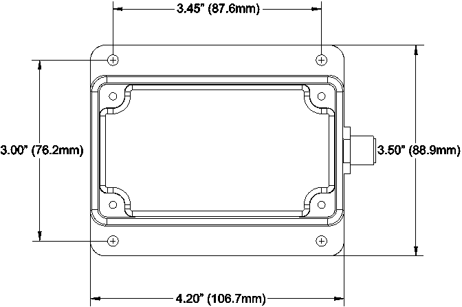
Figure 5 – Mounting Surface Template
10 Maretron (2 Year) Limited Warranty
Maretron warrants the CLM100 to be free from defects in materials and workmanship for two (2) years from the date of original purchase. If within the applicable period any such products shall be proved to Maretron’s satisfaction to fail to meet the above limited warranty, such products shall be repaired or replaced at Maretron’s option. Purchaser's exclusive remedy and Maretron’s sole obligation hereunder, provided product is returned pursuant to the return requirements below, shall be limited to the repair or replacement, at Maretron’s option, of any product not meeting the above limited warranty and which is returned to Maretron; or if Maretron is unable to deliver a replacement that is free from defects in materials or workmanship, Purchaser’s payment for such product will be refunded. Maretron assumes no liability whatsoever for expenses of removing any defective product or part or for installing the repaired product or part or a replacement therefore or for any loss or damage to equipment in connection with which Maretron’s products or parts shall be used. With respect to products not manufactured by Maretron, Maretron’s warranty obligation shall in all respects conform to and be limited to the warranty actually extended to Maretron by its supplier. The foregoing warranties shall not apply with respect to products subjected to negligence, misuse, misapplication, accident, damages by circumstances beyond Maretron’s control, to improper installation, operation, maintenance, or storage, or to other than normal use or service.
THE FOREGOING WARRANTIES ARE EXPRESSLY IN LIEU OF AND EXCLUDES ALL OTHER EXPRESS OR IMPLIED WARRANTIES, INCLUDING BUT NOT LIMITED TO THE IMPLIED WARRANTIES OF MERCHANTABILITY AND OF FITNESS FOR A PARTICULAR PURPOSE.
Statements made by any person, including representatives of Maretron, which are inconsistent or in conflict with the terms of this Limited Warranty, shall not be binding upon Maretron unless reduced to writing and approved by an officer of Maretron.
IN NO CASE WILL MARETRON BE LIABLE FOR INCIDENTAL OR CONSEQUENTIAL DAMAGES, DAMAGES FOR LOSS OF USE, LOSS OF ANTICIPATED PROFITS OR SAVINGS, OR ANY OTHER LOSS INCURRED BECAUSE OF INTERRUPTION OF SERVICE. IN NO EVENT SHALL MARETRON’S AGGREGATE LIABILITY EXCEED THE PURCHASE PRICE OF THE PRODUCT(S) INVOLVED. MARETRON SHALL NOT BE SUBJECT TO ANY OTHER OBLIGATIONS OR LIABILITIES, WHETHER ARISING OUT OF BREACH OF CONTRACT OR WARRANTY, TORT (INCLUDING NEGLIGENCE), OR OTHER THEORIES OF LAW WITH RESPECT TO PRODUCTS SOLD OR SERVICES RENDERED BY MARETRON, OR ANY UNDERTAKINGS, ACTS OR OMISSIONS RELATING THERETO.
Maretron does not warrant that the functions contained in any software programs or products will meet purchaser’s requirements or that the operation of the software programs or products will be uninterrupted or error free. Purchaser assumes responsibility for the selection of the software programs or products to achieve the intended results, and for the installation, use and results obtained from said programs or products. No specifications, samples, descriptions, or illustrations provided Maretron to Purchaser, whether directly, in trade literature, brochures or other documentation shall be construed as warranties of any kind, and any failure to conform with such specifications, samples, descriptions, or illustrations shall not constitute any breach of Maretron’s limited warranty.
Warranty Return Procedure:
To apply for warranty claims, contact Maretron or one of its dealers to describe the problem and determine the appropriate course of action. If a return is necessary, place the product in its original packaging together with proof of purchase and send to an Authorized Maretron Service Location. You are responsible for all shipping and insurance charges. Maretron will return the replaced or repaired product with all shipping and handling prepaid except for requests requiring expedited shipping (i.e. overnight shipments). Failure to follow this warranty return procedure could result in the product’s warranty becoming null and void.
Maretron reserves the right to modify or replace, at its sole discretion, without prior notification, the warranty listed above. To obtain a copy of the then current warranty policy, please go to the following web page:
http://www.maretron.com/company/warranty.php